The Institute of Corrosion would like to express their condolences to Family, friends and colleagues around the world of Lee Wilson FICorr who sadly passed away this week.
Lee was a professional in his field of corrosion control, Fellow of the Institute of Corrosion, and more recently regenerated the North East Branch of ICorr to which he chaired.
His knowledge, pro-active approach to problem solving, and general interaction with the corrosion world will be very much missed. “
Amr E. Saleh, Corrosion Engineer, Al-Masaood Oil & Gas Company, ADNOC Offshore, Abu Dhabi, UAE, Galal M Attia and Hany Ammar, Metallurgical and Materials engineering Dept., Faculty of Petroleum and Mining Engineering, Suez University, Suez, Egypt
Aluminum Galvalum III anodes are widely used in the Oil and Gas industry to protect carbon steel structures such as water tanks, vessels, pipelines and other onshore and offshore structures. These anodes need to be replaced after consumption, requiring the equipment to be taken out of service (shut down) to replace them, at high cost and time. Pure aluminum cannot function as
a galvanic anode as the formation of stable oxide films causes the electrochemical potential to shift to a very noble potential
(passivation).
However, the addition of activator elements can disrupt the oxide film formation and maintain the active electrochemical potential for the aluminum alloy. Therefore, by proper alloying, aluminum anodes can be used to supply cathodic protection current. [1]It has been reported that, alloying, grain refining, fabrication and anode material processing procedures, strongly affect the efficiency of sacrificial anodes. [2]
Research was carried out to investigate the effect of tin (Sn) addition at different concentrations to Galvalum III anodes, and the effect of heat treatment on aluminum anode efficiency.
(The efficiency of a galvanic anode depends on the alloy of the anode and the environment in which it is installed. The consumption of any metal is directly proportional to the amount of current discharged from its surface. For galvanic anodes, part of this current discharge is due to the cathodic protection current provided to the structure and part is caused by local corrosion cells on its surface).
Anode efficiency is defined as the ratio of metal consumed producing useful cathodic protection current to the total metal consumed. The efficiency of Galvalum III anodes, is around
85 %. [3].
This article reports the results of a study of four aluminum anode specimens (galvalium III) produced with different tin (Sn) concentrations (0%, 0.01%, 0.05% and 0.1%). Heat treatment was carried out by heating to a homogenisation temberature of 5100C for 5 hours, and after this, some samples were annealed by slow cooling in the furnace and other samples were quenched by rapid cooling to room temperature in a water bath.
Experimental procedures
Material and sample preparation
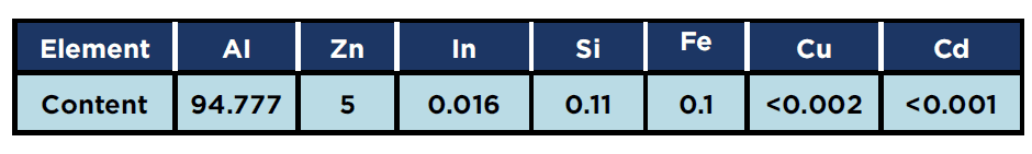
Aluminum Galvalum III anodes which had already been used for the cathodic protection of water tanks at a gas processing plant in Egypt, were used in the study and their composition is given in Table 1. Approximately, 1.2kg of the anode material was cut into small pieces for melting and preparation of the alloys used in the present work.
Table 1: Chemical composition of (Galvalum III) anode (wt.%)
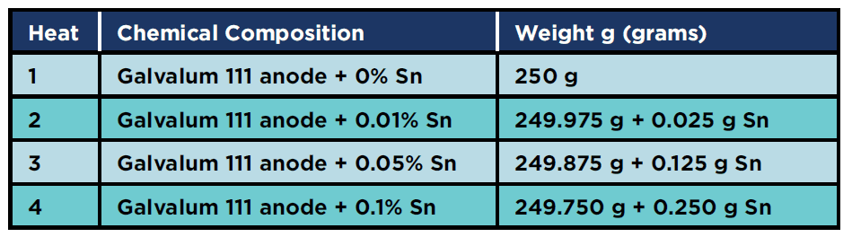
Four alloy compositions were prepared by melting this anode material using a graphite crucible in an electrical resistance furnace. The alloying element (commercially pure tin) was added after melting of anode material. The nominal chemical composition of all produced alloys is given in Table 2. It should be noted that, during the melting process, an average of 1.5% of the input material is added to compensate for the losses due to oxidation and evaporation of alloying elements.
Table 2: Concentrations of each heat
Samples were cast in an electric furnace at 5000C for 1 hour to increase the fluidity of aluminum alloy inside the mold. Each mold was divided to three sections, one for ‘as cast’ condition, and two sections for different heat treatments, homogenising and annealing.
Chemical composition analysis for all samples was verified by X-Ray Fluorescence (XRF). [7]
Heat treatment
The aim of the homogenising heat treatment process was to redistribute the alloying element evenly through the specimens. The homogenising temperature was 510°C, which was selected to be just under aluminum melting point (670 °C) to help the diffusion process. Once the whole part reached the homogenising temperature it was allowed to cool rapidly by water quenching, resulting in a homogenous super saturated alloy.
For the annealing heat treatment process, once the whole part reached the homogenising temperature it was allowed to cool slowly inside the furnace, resulting in a part that had a uniform internal structure.
Electrochemical testing
Electrochemical testing was carried out for all specimens (different concentrations and different heat treatment) to assess the most important characteristics for galvanic anodes. The testing was carried out according to NACE Standard TM0190-2012 Impressed Current Laboratory Testing of Aluminum and Zinc Alloy Anodes. [4]
This standard test method describes a laboratory procedure for determining the potential and current capacity characteristics of aluminum alloy anodes used for cathodic protection. It provides a mean for screening various batches of anodes to determine performance consistency on a regular basis from lot to lot.
A 16-cm3 sample of the aluminum alloy anode material was immersed
in synthetic seawater, at ambient temperature for two weeks (336 h).
See ASTM D1141-98 (Reapproved 2013) [5]. Potentials were measured periodically and current capacity determined. Anode potentials were measured with a standard Ag/AgCl reference electrode.
Anode current capacity was determined by the mass loss method. The total current passing through the system was measured by multi-meter.
Anode mass loss was determined at the end of the two-week test when the samples were removed, cleaned, and weighed.
Mass loss current capacities were determined from knowledge of the total charge passed through the system and the mass loss of the anode samples.
Calculation of Efficiency
Mass Loss Method: Anode current capacity was calculated for each sample as shown in the equation below
E: Current capacity (amperes. hours/gram)
I: current (amperes) averaged over 14 days
Wi: initial sample weight (grams)
Wf: final sample weight (grams)
Polarization Resistance testing (Tafel slope) was carried out for 1C, 4C, 4A and 4Q (see definition below) according to ASTM G59-97 Standard Test Method for Conducting Potentio-dynamic Polarization Resistance Measurements. [6]
The specimens tested were
1C: Galvalum III + 0 % Sn (As cast condition)
4C: Galvalum III + 0.1 % Sn (As cast condition)
4A: Galvalum III + 0.1 % Sn (Annealed condition)
4Q: Galvalum III + 0.1 % Sn (Quenched condition)
These specimens were selected for this test to differentiate corrosion behaviour between 1C without tin, and 4C with 0.1% tin addition. 4C, 4A and 4Q were selected to assess the effect of heat treatment on corrosion rate.
Microstructure analysis (SEM and EDX)
Specimens (detailed below) were mounted, ground, polished and etched (using HF 40%, HNO370%, HCL 38% and distilled water) to reveal the original microstructures of the alloys and observe the distribution of phases and alloying elements.
1C: Galvalum III + 0 % Sn (As cast condition)
1A: Galvalum III + 0 % Sn (Annealed condition)
1Q: Galvalum III + 0 % Sn (Quenched condition)
4C: Galvalum III + 0.1 % Sn (As cast condition)
4A: Galvalum III + 0.1 % Sn (Annealed condition)
4Q: Galvalum III + 0.1 % Sn (Quenched condition)
Observations were made visually and by SEM.
Specimens 1C, 4C, 4A and 4Q were also analysed using EDX to identify the phases which were formed.
Results and discussion
Current capacity results As cast condition
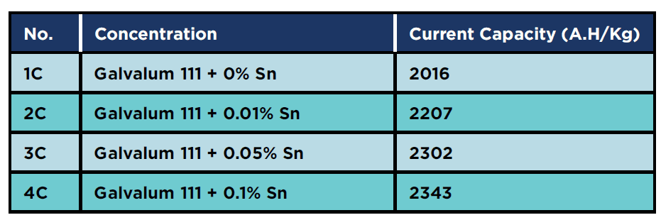
The electrochemical test results show that adding tin enhances the current capacity of Galvalum III anodes as shown in Table 3
The increase in current capacity may be attributed to the effect of tin addition as a depassivating element in neutral sea water. The presence of tin as alloying element will reduce the ionic resistance of the oxide film on the investigated alloys.
There are different views on the role of tin, but it is generally accepted that the creation of additional cation vacancies by including tin as quadrivalent Sn4+ is responsible for improving the cathodic protection properties. It was clearly shown that the decrease in surface free energy with the addition of tin to Galvalum III anode alloy (Al + 5% Zn) is the principal reason for the increase in the cathodic protection properties of these cast alloys.
Table 3: Current capacity for as cast condition specimens
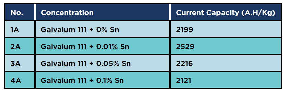
Annealed condition
The electrochemical test results showed that the 2A (Al-5%Zn – 0.01 % Sn) sample had the highest current capacity of all the annealed samples, as shown in Table 4. It is clear that the presence of 0.01 % tin gives the highest current capacity of all the measured annealed specimens.
Table 4: Current capacity for annealed condition specimens
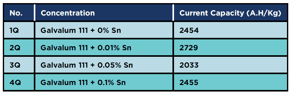
Quenched condition
The electrochemical test results also showed that the 2Q (Al-5%Zn – 0.01 % Sn) sample had the highest current capacity of the four quenched samples as shown Table 5. Also, the alloy 2Q, with 0.01% tin addition hds the highest current capacity of all the investigated alloys.
The 3Q current capacity was low so the electrochemical test was repeated for this specimen, and the result was also relatively low in the second trial (1850 A.H/Kg).
Table 5: Current capacity for Quenched condition specimens
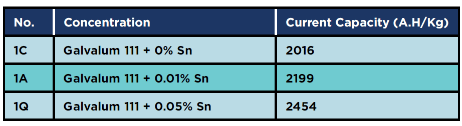
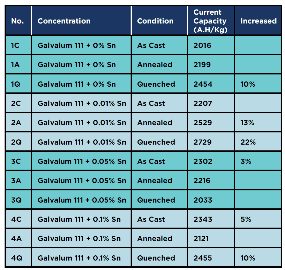
Effect of no tin addition at different heat treatments
Table 6 shows the results of the current capacity measurements for zero percent tin alloys, in the as cast, annealed, and homogenised conditions (viz alloys 1C, 1A and 1Q respectively). It is obvious that, heat treatments in general improve the distribution of alloying elements, the distribution of second phase precipitates, and also eliminate the casting defects such as macro and micro segregation. It is clear that quenched condition (1Q) gives the highest current capacity.
Table 6: Current capacity for original specimens
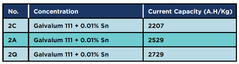
Effect of 0.01% in addition at different heat treatment
Table 7 summarises the effect of 0.01% tin addition on the current capacity. The current capacity increased by about 15% after annealing and by about 24 % after homogenising heat treatment, relative to the as cast conditions. Such an increase in in current capacity could be attributed to the effect of heat treatment which eliminate the segregation and inhomogeneity in the distribution of alloying elements in the as cast condition, in addition to the increase in solid solubility of alloying elements after quenching from solution treatment temperature.
Table 7: Current capacity for 0.01% tin specimens
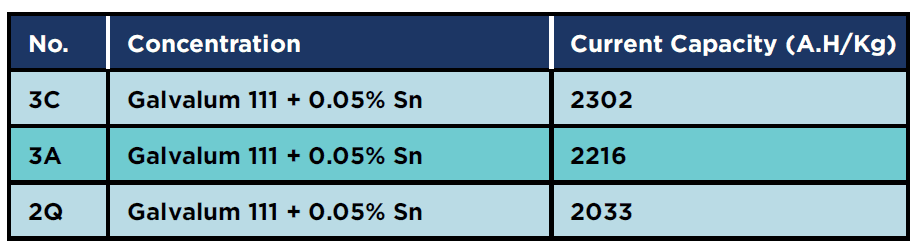
Effect of 0.05% tin addition at different heat treatment
Table 8 shows the results of the current capacity measurements for 0.05% tin alloys in as cast (3C), in annealed (3A) and in as quenched conditions (3Q). There is no drastic change in the measured values, in contrast to the results obtained from the current capacity measurements for the alloy groups (1) and (2) where the current capacity increased by heat treatment. The explanation for such behavior was not found in the available literature. The results of repeated electrochemical measurements for this alloy group gave approximately the same results.
Table 8: Current capacity for 0.05% tin specimens
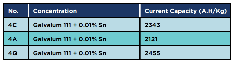
Effect of 0.1% tin addition at different heat treatment
Table 9 summarizes the effects of 0.1% tin addition on the value of current capacity. The measured values are 2343 for as cast (4C), 2121 for as annealed (4A) and 2455 A.H/Kg for as Quenched (4Q). Again there is no drastic change in the measured values, in contrast to the results obtained from the current capacity measurements for the alloy group (1) and (2) where the current capacity increased by heat treatment. It must be notice that, quenched condition (4Q) gives relatively higher current capacity than as cast and annealed conditions.
Table 9: Current capacity for 0.1% tin specimens
Current capacities of all specimens compared with Galvalum III
Table 10 shows the electrochemical test results for all specimens. It is clear that quenched alloy (2Q), which contains 0.01% tin addition, has the highest measured value of current capacity, with about 22 % increase over that measured for Galvalum III. In general quenching heat treatment drastically improves the current capacity of investigated alloys
Table 10: Current capacity for All Specimens compared to Galvalum III Current Capacity 2232 A.hr/Kg
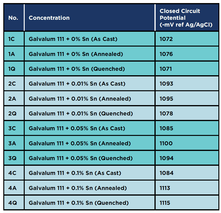
Mean value of closed circuit potential of all specimens
Table 11 shows the mean value of the closed circuit potential for all specimens connected to carbon steel coupons, and as shown they all achieved the cathodic protection criteria according to NACE SP0169, which states that protection potential should be more negative than -760 mV regarding to Ag/AgCl reference electrode.
The highest negative potential mean value was achieved with specimen 4Q, with a value of – 1115 mV.
Table 11: Mean measured closed circuit potential for All Specimens
Microstructure analyses (SEM and EDX)
As cast condition microstructure Analysis:
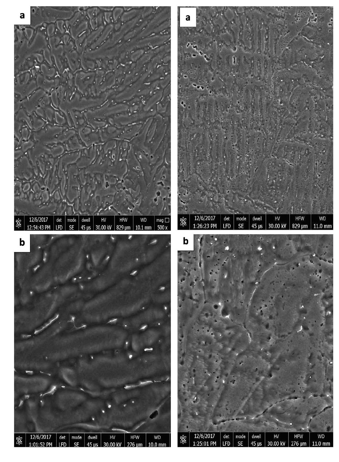
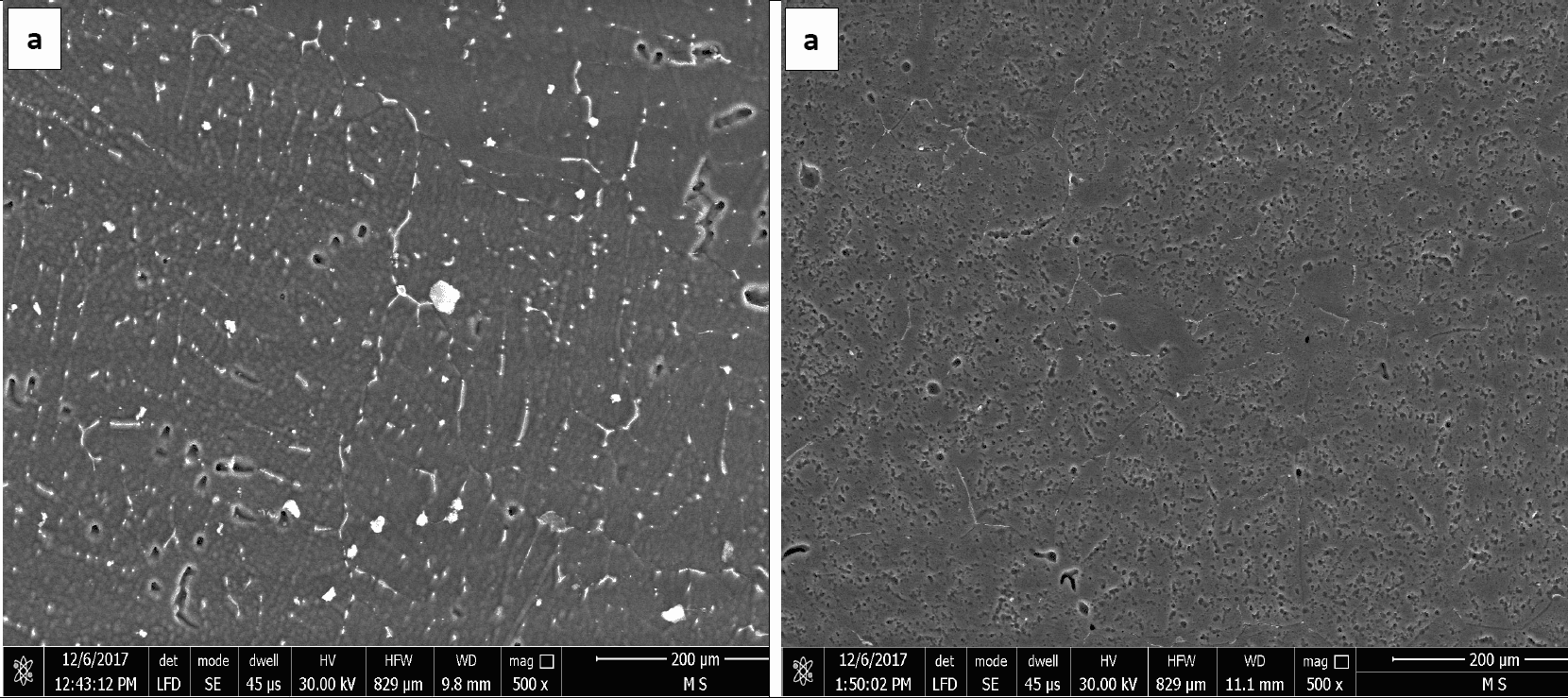
Figures 1 and 2 represent the microstructures of Galvalum III without tin addition (1C as cast condition) and of Galvalum III with 0.1 % tin addition (4C as cast condition) respectively. The microstructures developed after casting of both alloys are distinctly different in grain morphology, distribution, and nature of second phase precipitates.
The microstructure morphology of Galvalum III alloy 1C appears to be cellular-dendritic structure and that of 4C appears to be dendritic. The difference in microstructure morphology may be due to the presence of 0.1% tin in alloy 4C, which may affect the surface properties of solidified aluminum solid solution primary phase. Both alloys (1C and 4C) are composed from aluminum – solid-solution matrix and second-phase dispersed precipitates. Table 1 gives the chemical composition of Galvalum III alloy. Iron and silicon are the most common impurities found in aluminum. The solubility of iron and silicon in the solid state are very low and therefore, most of the iron and silicon which are present in Galvalum III appear as an intermetallic second phase in combination with aluminum and often other elements. The presence of indium in both alloys, which is not soluble in aluminum, may be responsible for the presence of the white colored second phase precipitates at inter dendritic spaces as it seen in Figures 1 and 2, while the presence of tin in alloy 4C (figure 2) could be responsible for the presence of other precipitates which are dispersed inside grains and between the dendritic arm spacing.
The precipitates morphology appears to be spheroidal shaped particles, rode like particles and agglomerated spheroidal particles.
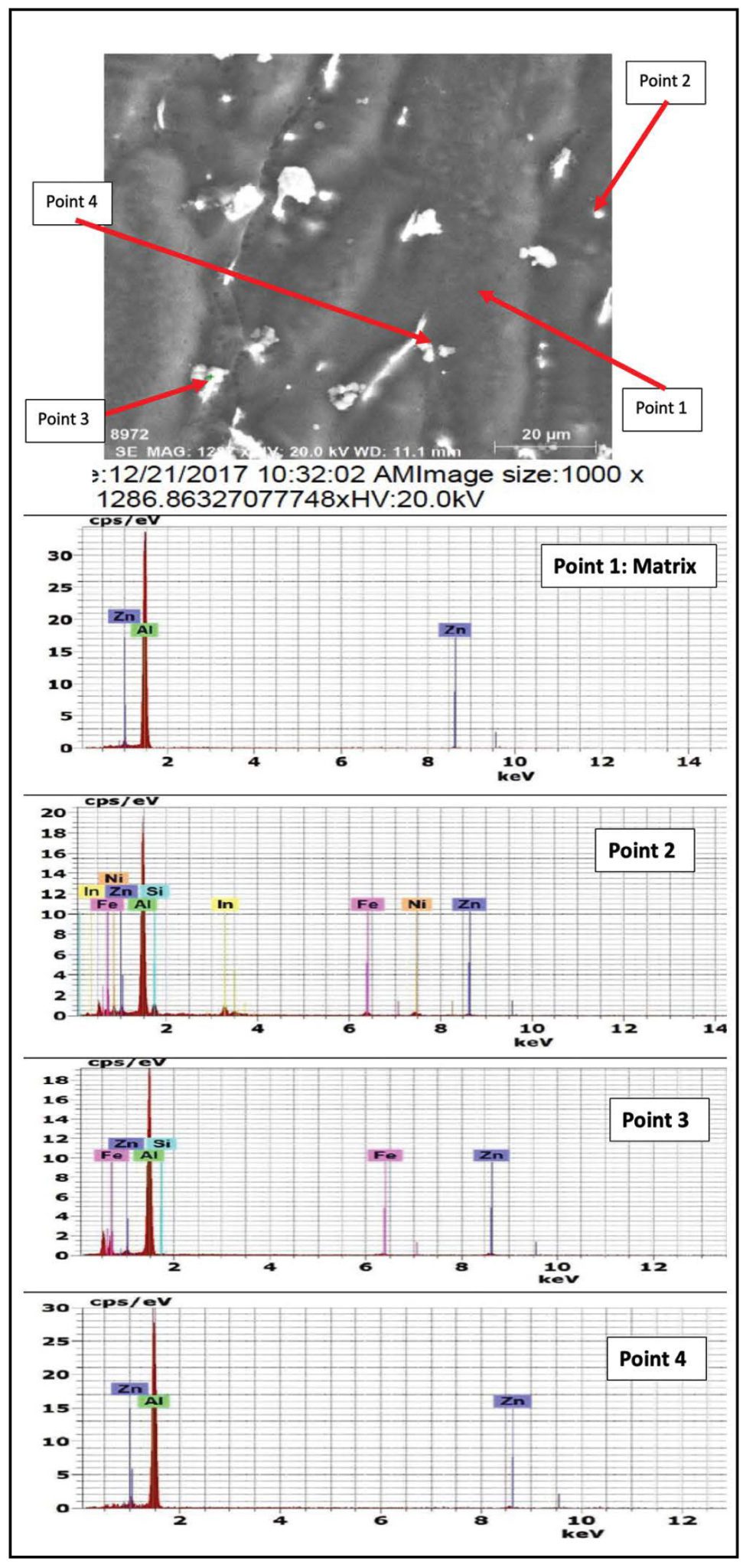
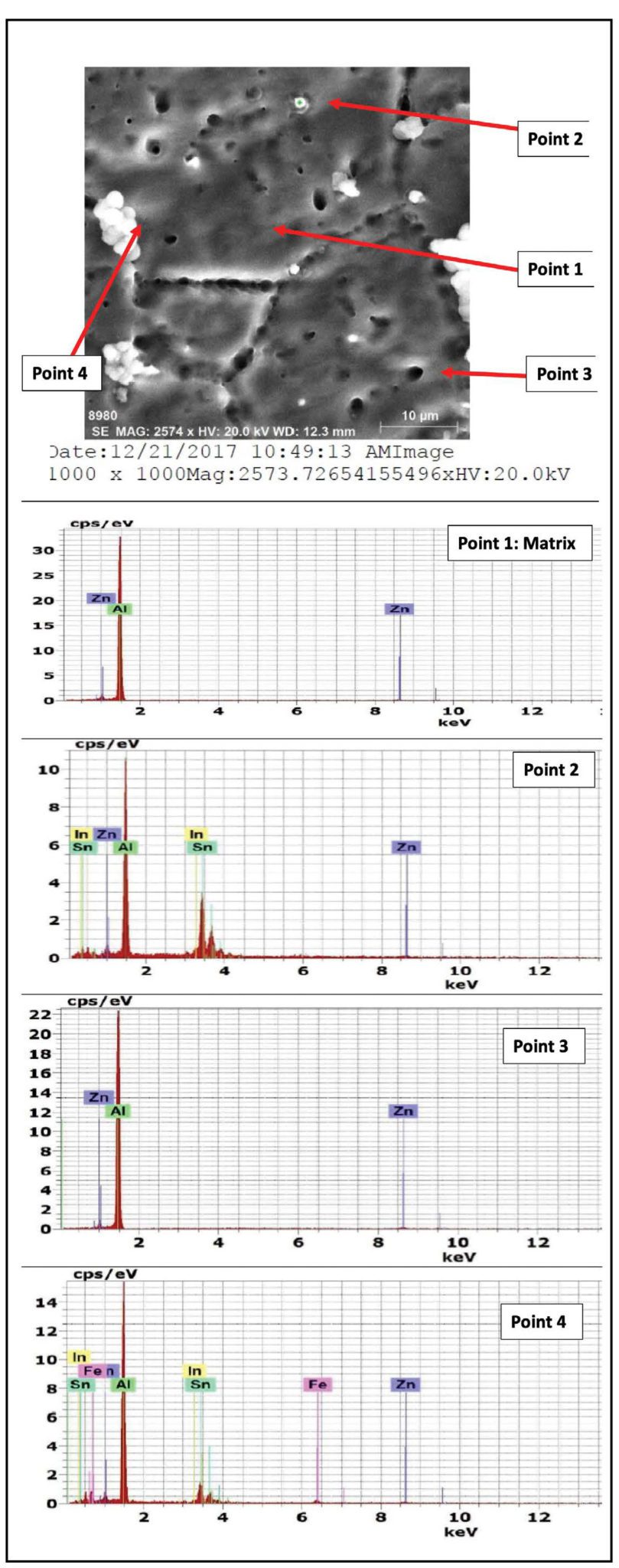
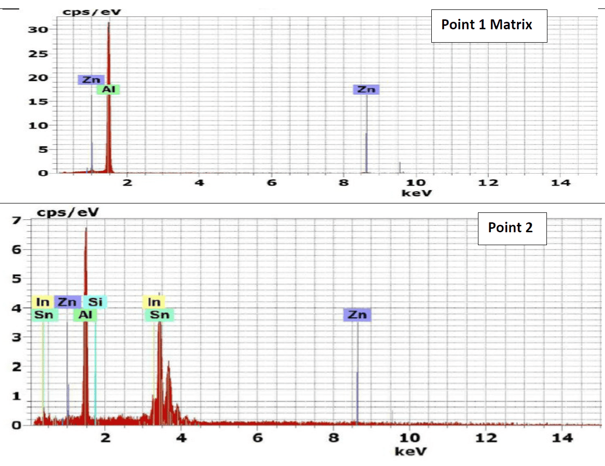
The results of energy dispersive X-Ray (EDX) phase analysis for the as cast structure of Galvalum III alloys 1C and galvalum III + 0.1 % tin alloy 4C are given in Figures 3 and 4 respectively.
The matrix point analysis of points 1 and 4 in alloy 1C figure 3 and points 1 and 3 in alloy 4C figure 4 showed identical chemical composition of aluminum zinc solid solution for both alloys. It clear that all tin additions in alloy 4C are presented only in the precipitated particles inside primary aluminum solid solution, and at the grain boundaries of the primary phase. The EDX analysis of the precipitates at points 2 and 3 which are present in microstructure of alloy 1C (the as cast structure of Galvalum III) in Figure 3 are not completely identical.
The precipitates present at point 3 may be considered as agglomeration of insoluble iron and silicon elements combined with matrix alloying elements of aluminum and zinc forming intermetallic compounds, while the precipitates present at point 2 have spheroidal shape, which is not similar to point 3 in shape and composition.
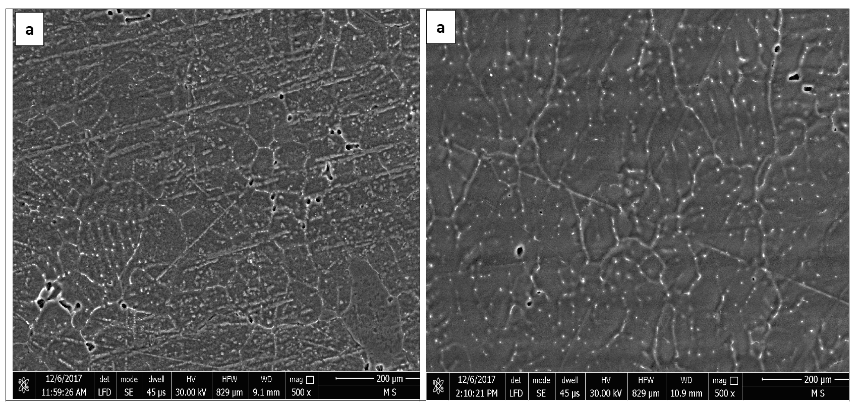
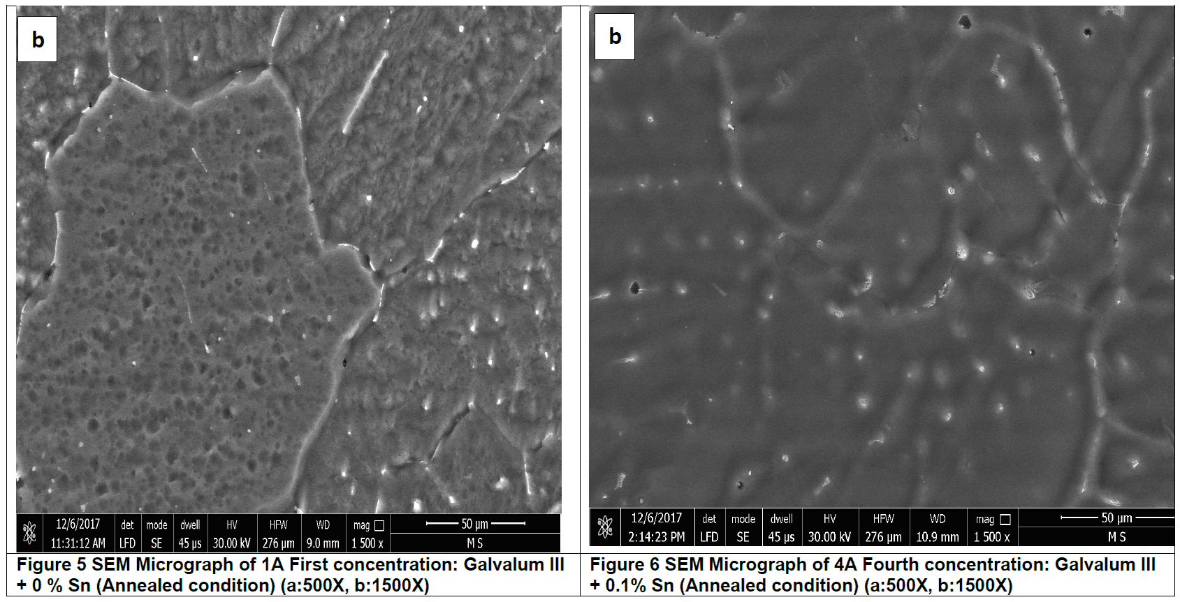
Annealed condition microstructure Analysis
Figures 5 and figure 6 represent microstructure of annealed Galvalum III alloy no. 1A and the annealed Galvalum III + 0.1% Tin alloy no. 4A respectively. Annealing process for both alloys was carried out at 510 οC for 5 hours followed by furnace cooling. The microstructures developed after annealing of both alloys are approximately similar. The microstructure morphology consists mainly from equi-axed grains of primary aluminum solid solution and massive precipitates located inside grains and at grain boundaries.
The high annealing temperature and relatively long annealing time give the driving force for equi-axed grain formation.
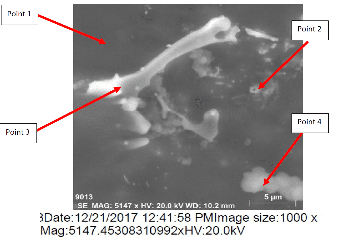
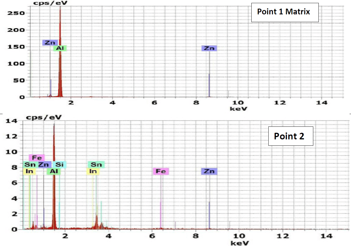
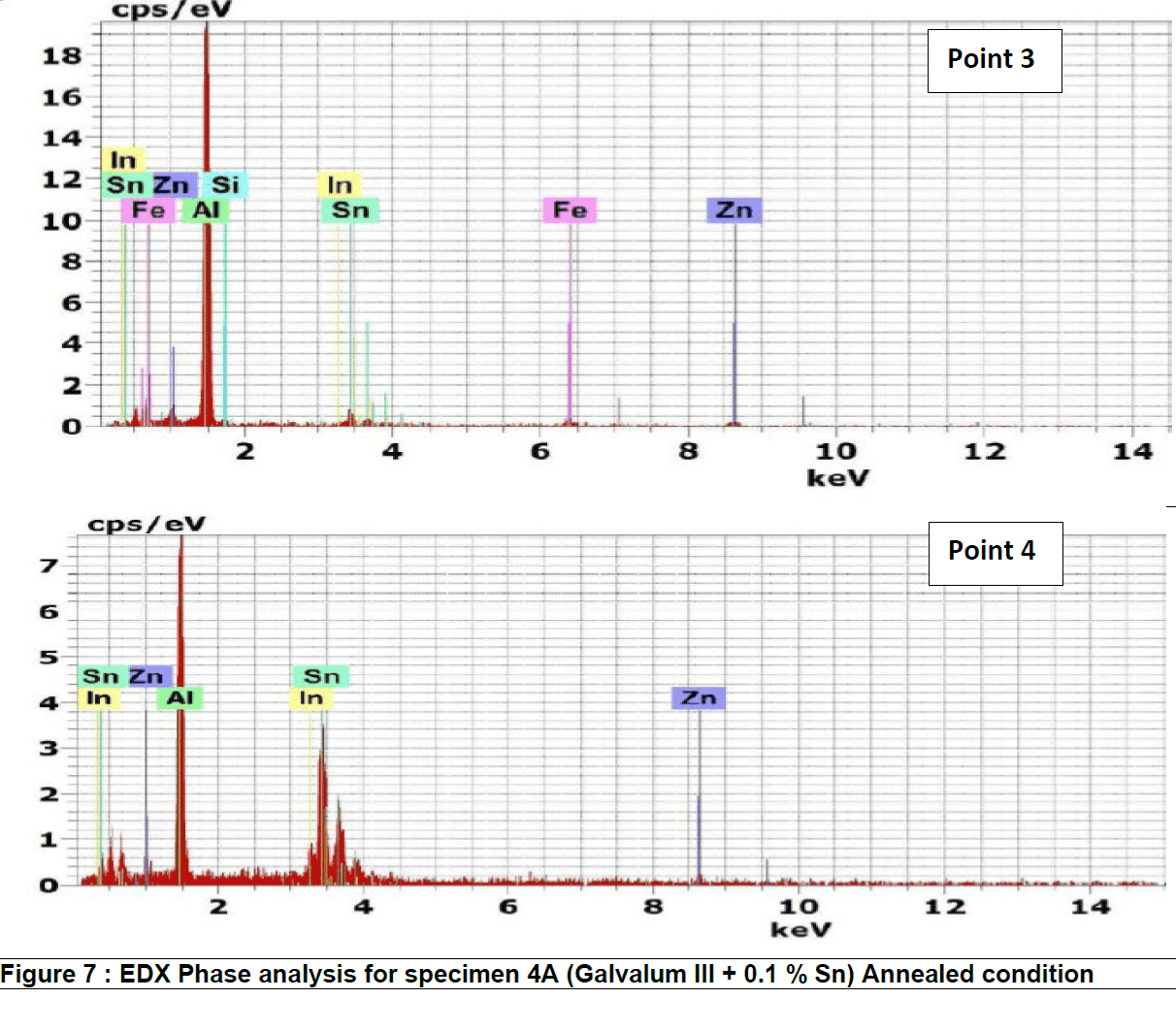
Figure 7 represents the energy dispersive X-Ray (EDX) phase analysis of annealed alloy no. 4A. EDX analysis revels that, the matrix phase analysis, point 1, composed from aluminum – zinc solid solution while the second phase precipitates in point 2, 3 and 4 are intermetallic compounds formed as result of interaction between the base metal alloying elements of aluminum and zinc mainly with other segregated insoluble elements of indium, tin, iron and silicon.
When Galvalum III, alloy no.1, and Galvalum III + 0.1 Tin, alloy no. 4, are heated to 510 οC temperature which is selected to be just above the solvus line, only one single phase is thermodynamically stable. After 5 hours holding time at such homogenizing temperature all alloying elements must be dissolved in solid solution. When a solid-solutionized sample is rapidly cooled to room temperature below solvus line two phases are thermodynamically stable (alpha and beta). At room temperature in equilibrium conditions, the solubility of Zn in Al amounts 0.85 at%, and the one of Al in Zn is smaller than 0.5 %.
The rapid cooling process will produce non-equilibrium condition which gives thermodynamically unstable structure. The rapidly cooled microstructures of specimen no. 1Q and 4Q reveal thermodynamically unstable microstructures. The rapidly cooled microstructures of both alloys are composed mainly from super saturated solid solution and fine dispersed precipitates.
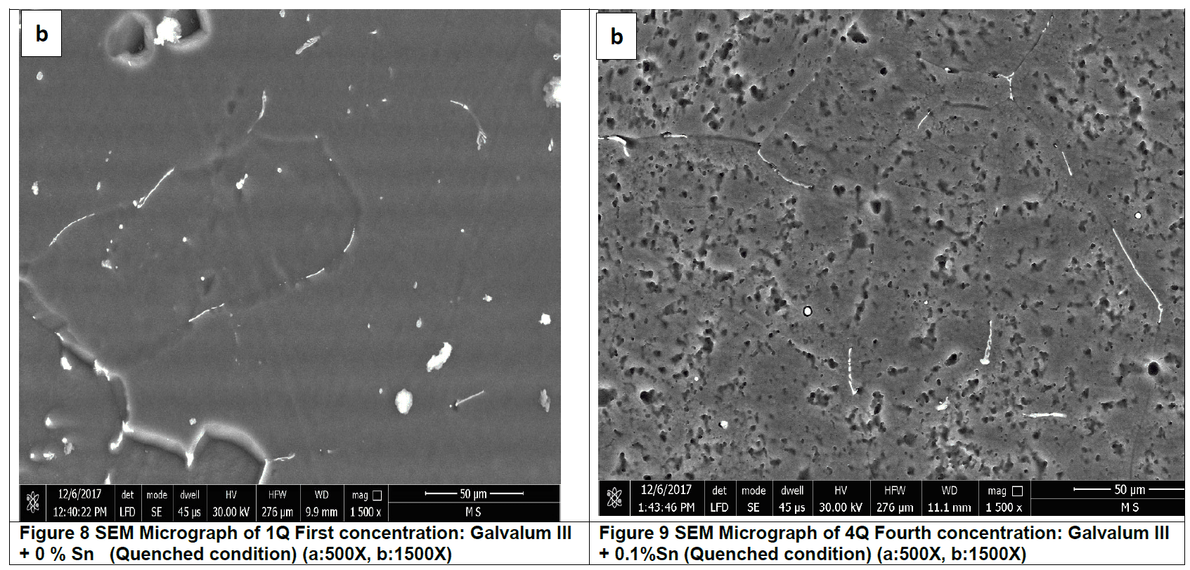
The microstructure of Galvalum III after rapid quenching as given in figure 8 (1Q) is clearly different in details comparing to the microstructure of Galvalum III + 0.1% Tin after same treatment as given in figure 9 (4Q). The main difference lies in the shape and distribution as well as the chemical composition of precipitates.
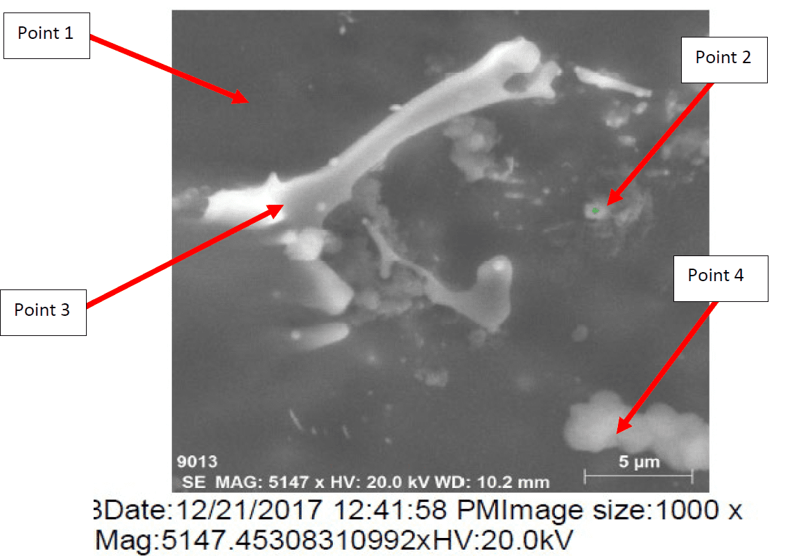
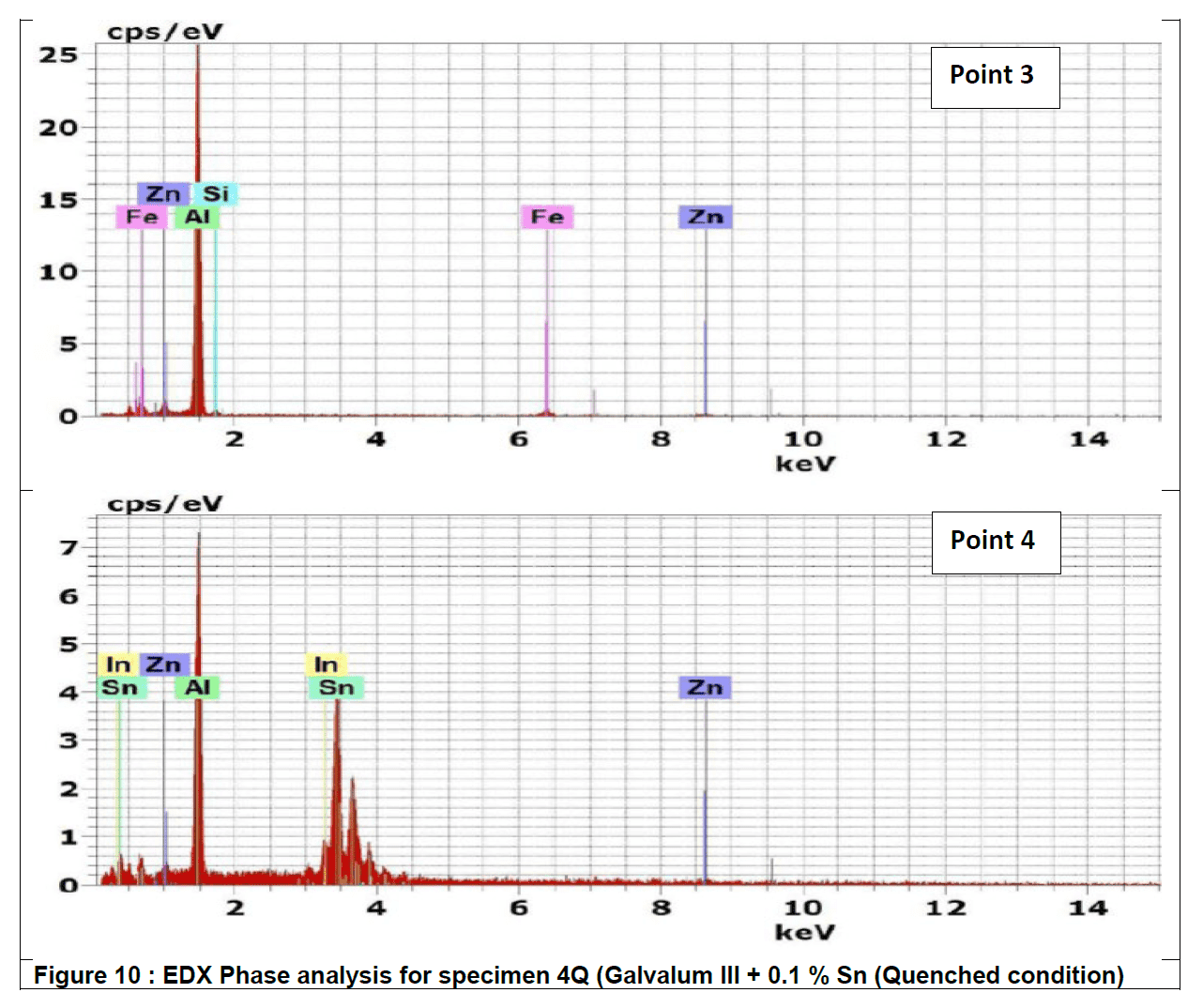
Figure 10 represents the energy dispersive X-Ray (EDX) phase analysis of the as quenched alloy no. 4Q. The EDX analysis revels that, the matrix phase analysis, point 1, composed from aluminum – zinc solid solution while the second phase precipitates in point 2, 3 and 4 are intermetallic compounds formed during rapid cooling as result of interaction between the base metal alloying elements of aluminum and zinc mainly with other segregated insoluble elements of indium, tin, iron and silicon.
The precipitate particle which is present at point 3 contains iron in addition to Silicon and base metal alloying elements Aluminum and Zinc and don’t contain Tin or Indium while the precipitate analysis of point 2 and 4 contain Tin and Indium and don’t contain iron or silicon.
The details mechanism which may explain the reasons for the presence of such different precipitate is not found in available literatures.
Conclusion
The addition of tin increases the activation of Galvalum III (Al-Zn-In) alloy, and the extent of activation increases with increasing tin content. Results confirm that the current capacity and efficiency of aluminum Galvalum III anodes increases by 16 % with the addition of 0.1 % tin without heat treatment.
Homogenisation heat treatment gives higher current capacity and efficiency than ‘as cast’ and annealed (in most investigated alloys).
The highest current capacity is 2729 A.hr/kg and it was achieved after homogenisation treatment of the alloy containing 0.01 % tin. After quenching of the alloy containing 0.01% Sn, the current capacity increased by 23.6 % compared with the ‘as cast’ condition for the same alloy and 22% compared with the as received Galvalum III.
Corrosion rate decreased from 0.21 mm/year in case of Galvalum III without tin addition (cast condition) to 0.15 mm/year in case of Galvalum III with 0.1% tin, which reflects the benefit of tin addition on decreasing self-corrosion of the anode and enhancement of the efficiency.
Corrosion rate of heat treated anodes (annealed and quenched) is decreased significantly from 0.15 mm/year for cast condition to 0.005 mm/year, and 0.003 mm/year for quenched and annealed respectively, reflecting also the benefit of heat treatment in decreasing self-corrosion of anodes and enhancement the efficiency.
The increase in current capacity of heat treated alloys could be attributed to the homogenised distribution of second phase precipitates and the super saturation of aluminum solid solution matrix by the alloying elements, and the beneficial elimination of the internal defects resulting from the casting process like voids and dislocations in the alloy, therefore improving the current capacity of the alloy.
References
[1] NACE International, CP 3- Cathodic protection technologist Course Manual, Houston, TX: NACE International,2008
[2] DNV Recommended Practice RP B401 (2010). Cathodic Protection Design, Det Norske Veritas Industry AS, Hovik 2010.
[3] NACE International, CP 2 – Cathodic Protection Technician. Houston, TX: NACE International, 2012.
[4] NACE International, NACE Standard TM0190-2012 Impressed Current Laboratory Testing of Aluminum and Zinc Alloy Anodes. Houston, TX: NACE International, 2012.
[5] ASTM International, ASTM D1141-98 (Reapproved 2013) Standard Practice for the Preparation of Substitute Ocean Water. West Conshohocken, PA: ASTM International, 2013.
[6] ASTM International G59 (Reapproved 2003) Standard Test Method for conducting potentiodynamic Polarization Resistance Measurements.
[7] Handheld XRF Analyzers MET7000 Series User Manual, Oxford Instruments.
[8] ASM Metal Handbook 2004 ASM International, Vol. 9, Metallography and Microstructure.
Aberdeen events coming up in October and November 2022 include:
25/10/2022 – Dene Halkyard (Flexitallic) will present Flange Face Corrosion in Seawater and Hydrocarbon Environments related to Gasket Material Selection. ICorr Aberdeen Technical Event (Zoom Mtg) Start 18:00: Finish at 19:30.
16/11/2022 – Prafull Sharma (CorrosionRADAR) will talk on The Era of Remote Corrosion Monitoring. Joint ICorr Aberdeen Technical Event (Zoom Mtg) with Joint Meeting with IOM3/MIS. Start 18:00: Finish at 19:30.
24/11/2022 – YEP 2022 Final Presentation – Case Study Competition. Palm Court Hotel, 81 Seafield Rd, Aberdeen AB15 7YX. Start 16:00: Finish at 20:00.
ICorr HQ will notify all ICorr Members shortly of Event Details / Registration Details.
To join the Aberdeen Branch Mailing List, please contact: icorrabz@gmail.com
Advance your organisation’s capability in microbial corrosion management with this high impact, ICorr training programme. Designed for professionals in operations, integrity, inspection, management, design, R&D, consultancy, and utilities. The course equips participants to:
Identify MIC drivers across a wide range of systems
Implement targeted monitoring, mitigation, and control strategies
Lead investigations supported by robust, defensible evidence
Influence organisational policies and strengthen MIC governance
Align internal practices with global standards and best-in-class methodologies
Delivered by a leading subject matter expert and aligned with ICorr recognised competency framework, this course blends technical depth with practical application—empowering participants to protect assets, enhance performance, and drive meaningful organisational improvement. It contributes to Continuing Professional Development (CPD).
Certification Opportunity
Participants who successfully pass the final examination will earn the ICorr Certified MIC Technologist credential—a globally recognised mark of excellence in microbial corrosion management and a valuable step toward professional chartership.
We use cookies to optimize our website and our service.
Functional
Always active
The technical storage or access is strictly necessary for the legitimate purpose of enabling the use of a specific service explicitly requested by the subscriber or user, or for the sole purpose of carrying out the transmission of a communication over an electronic communications network.
Preferences
The technical storage or access is necessary for the legitimate purpose of storing preferences that are not requested by the subscriber or user.
Statistics
The technical storage or access that is used exclusively for statistical purposes.The technical storage or access that is used exclusively for anonymous statistical purposes. Without a subpoena, voluntary compliance on the part of your Internet Service Provider, or additional records from a third party, information stored or retrieved for this purpose alone cannot usually be used to identify you.
Marketing
The technical storage or access is required to create user profiles to send advertising, or to track the user on a website or across several websites for similar marketing purposes.