Although we are at the start of the journey with ABRACO, the work continues to get more of the ICorr training courses into Brazil. Lucia Fullalove would like to thank Argyll Ruane and all her ICorr colleagues for the support and trust to turn the partnership with ABRACO into a reality. Especially, Bill Hedges, Kevin Harold, Gareth Hinds, David Horrocks, Keith Wagner, Brian Wyatt and John Fletcher.
Carbon steel is widely used a construction material of choice for buildings due to its inherent strength. Steel columns, trusses, girders and beams are the critical building components, failure of which usually leads to progressive collapse of the local and global structures. However, steel has high thermal conductivity which can cause it to lose its structural strength and stiffness as temperature increases. Expansion can also occur.
A non-uniform temperature distribution leads to thermal curvature. Any resistance to free movement of axial thermal expansion will induce internal stresses within the steel member making it frangible. The steel critical temperature for fire protection is the temperature that can cause structural collapse in a fire, and is often taken as 538 °C, as per ASTM E119, which corresponds to the point where it loses 50% of its load bearing capacity.
It is important to understand its mechanical and physical properties to understand how temperature affects steel. The melting point of steel is 1540 °C. Critical temperature is 720 °C, at 538 – 566 °C, carbon steel only retains about 50% of its yield strength. Steel can regain 100% strength if temperature does not exceed 720 °C.
Typical grades of structural steel are A36, A572, A588 and A514. They have yield strengths of 33000-35000 psi, and tensile strength 360000-70000 psi.
Rapid cooling of the steel elements heated between 704 and 843 °C during firefighting operations can also lead to some of the steel microstructure transform into martensite which increases hardness, but introduces brittleness. Below this temperature this transformation does not occur.
The purpose of PFP is to slow down propagation of heat to the structure bearing materials, e.g. steel beams and columns, to give time to evacuate the building before any catastrophic collapse of structural components could occur. Typically, the PFP materials are designed to withstand up to 2 hours of fire exposure per BS 476: Part 21, AS1530 Part 4, and up to 3 hours per ASTM E119 for intumescent products and up to 4 hours for cementitious products.
Most of the PFP materials used can be broken down into the three main categories:
• Cementitious products
• Mineral and fibre board systems
• Intumescent coatings
Cementitious products include cement and concrete, as well as lightweight materials such as mineral fibre, vermiculite or perlite. These products have relatively low thermal conductivity slowing the transmission of heat to the underlying structural steel. Lightweight mesh reinforcement may be required to increase durability for the structures subject to vibration or where mechanical damage is likely.
Fire protection boards are mineral boards (i.e. made of calcium silicate or calcium sulphate) reinforced with fibres and fillers, and can be further optimised for durability, e.g. resistance to humidity and freeze-thaw. The boards are manufactured in the controlled environment at a factory with strict tolerances and measurements. They require extensive supporting constructions, e.g. noggings, and require glue, staples, nails, etc. to be held together. It is typically easy to inspect their quality of installation.
Intumescent (which means “swell up”) coatings are composed of inorganic components contained in a polymer matrix: a combination of an acid source (ammonium phosphate, APP), a carbon source (pentaerythritol, PER) and a blowing agent (melamine). At the early stages of a fire, a large amount of thermal energy is absorbed by the coating, whose temperature increases rapidly. When the temperature of the coating reaches a critical temperature, the polymer matrix melts and degrades to form a viscous fluid. The inorganic acid source in the coating undergoes thermal decomposition normally at temperature of 100-250 °C. At temperature 280 – 350 °C, the blowing agent within the coating decomposes to release large amounts of gas of which some fraction is trapped within the molten matrix. The molten fluid hardens and releases residual volatile to form char. Convective currents are suppressed, and the thermal radiation does not have a “direct” path through the char to the substrate. This behaviour is complex and until now no agreeable model is available to simulate it.
Intumescent coatings are lightweight and can be applied in relatively thin coats. Other advantages include attractive appearance, and small volume occupation. They can easily follow the geometry of structural steel and are generally of relatively low cost. Intumescent coatings can be applied by airless spray, roller or brush, and cure and dry rapidly. Standard QA/QC requirements apply for surface preparation, application and inspection. Workshop application of these coatings has the advantage of better controlled application conditions. However, any structural materials with pre-applied intumescent coatings require careful transportation to minimize damage in transit.
Fireproofing coatings are tested for durability using time-temperature curves in accordance with UL 1709 for hydrocarbon fire exposures. ASTM E-119 is no longer used, as it does not adequately represent the fire exposure experienced in oil and chemical facilities. ASTM E-119 time-temperature curve however can still be used for non-hydrocarbon fires.
Dmitry Sidorin
This series of articles is intended to highlight industry wide engineering experiences, practical opinions and guidance, to allow improved awareness for the wider public and focused advice to practicing technologists. The series is written by ICorr Fellows who have made significant contributions to the field of corrosion management. The articles in this issue feature contributions from Bijan Kermani and Dmitry Sidorin.
An overview materials optimisation in CCS
A net-zero energy system to hinder or mitigate global warming driven by burning fossil fuel requires a step change in the way energy is being produced and used. This can only be achieved with a broad suite of technologies including improved energy efficiency, introduction of renewable energy and nuclear power. No mitigation option alone will achieve the desired reduction targets, however, they can be made
more influential when complemented by carbon capture and storage
(CCS) process.
CCS with sequestration can contribute both to reducing emissions and to removing CO2 to balance emissions – a critical part of “net” zero goals. CO2 sequestration is a process by which CO2 is removed from the atmosphere and stored indefinitely in underground locations primarily by means of pipelines. In addition to political and environmental incentives, CO2 sequestration is being considered in tertiary recovery for enhanced oil recovery (EOR) to produce residual hydrocarbon. Many oil and gas operators are looking at materials optimisation for such applications.
This Fellow’s Corner combines current status of corrosion threats and materials options for CO2 pipeline transmission and includes a simple roadmap enabling materials optimisation and outlining any technology gaps that may exist. It starts by describing sources of CO2, means of capture, methods of transportation and sequestration.
Sources of CO2, Capture and Sequestration
CO2 emission arises primarily from human activity and mainly from the combustion of fossil fuels used in different industrial sectors. CO2 is also emitted during certain industrial processes like cement manufacture or hydrogen production and during the combustion of biomass.
The first step in sequestration is CO2 capture. This is done through potentially numerous schemes, some commercially available at present, but all with a significant cost penalty. Capture from the atmosphere is done through biological, chemical or physical processes. The capture system may conveniently be divided into three categories (i) post combustion capture (scrubbing), (ii) pre-combustion capture and (iii) oxyfuel capture, details of which are beyond the scope of the Fellow’s Corner.
Having captured CO2, it needs to be transported and stored for long periods. This can be achieved by sequestration, a process by which CO2 removed from the atmosphere is injected and stored indefinitely. There are currently more than 70 CO2 injection projects in the US, injecting more than 35 million tons of CO2 annually, primarily for EOR.
Briefly, sequestration methods includes (i) geological sequestration, (ii) CO2 EOR, (iii) deep ocean sequestration, (iv) mineral and biological sequestration and (v) terrestrial sequestration again, details of which are beyond the scope of the Fellow’s Corner.
While CO2 has been injected into various geologic formations for decades for EOR purposes and acid gas disposal, the idea of permanent CO2 storage, or sequestration, for the purpose of mitigating global climate change is a fairly novel one with few commercial-scale prototypes upon which to draw guidance in the development of a regulatory framework.
Means of Transportation
Once captured and compressed, CO2 must be transported to a long term storage site as schematically shown in Figure 1 (below). In principle, transmission may be accomplished by pipelines, tankers, trains, trucks, compressed gas cylinders, as CO2 hydrate, or as solid dry ice. However, only pipeline and tanker transmission are reasonable economical options for the large quantities of CO2 associated with, for example, a 500MW power station. Trains and trucks could be used in the future for the transport of CO2 from smaller sources over short distances.
Pipelines
CO2 transmission by pipeline and injection into reservoirs began several decades ago. More than 40 million tons per year of CO2 are currently transmitted through high pressure CO2 pipelines, mainly in North America. Most of the CO2 obtained from natural underground sources is used for EOR.
The Weyburn pipeline, which transports CO2 from a coal gasification plant in North Dakota, USA to an EOR project in Saskatchewan, Canada is probably the first demonstration of large-scale integrated CO2 capture, transmission, sequestration and storage.
Ship Tankers
Ships are now used on a small scale for the transport of CO22 . Large scale transport of CO2 from power stations located near appropriate port facilities may occur in the future.
CO2 would be transported as a pressurised cryogenic liquid, for example at approximately 6 bar and -55°C. Ships offer increased flexibility in routes, avoid the need to obtain rights of way, and they may be cheaper, particularly for longer distance transportation. Ships similar to those currently widely used for transportation of liquefied petroleum gas (LPG) and liquefied natural gas (LNG) could be used to transport CO2.
Corrosion Threats and Severity
Dry CO2 is non-corrosive and relatively easily handled using conventional grades of carbon and low alloy steels (CLASs). However, in the presence of water, the situation is more complicated and system corrosivity would depend on water solubility of the CO2/H2O mixture and therefore, materials used in CCS systems can be subject to corrosion threats in which materials optimisation can take a centre stage.
CO2 readily dissolves in water to form carbonic acidic solution that is highly corrosive to many engineering materials. The accelerating effect of CO2 corrosion is a particularly important safety issue when considering the maintenance schedules and operating life expectancies for pipelines that were not originally designed for CO2 transmission use. Choice of materials for handing CO2 is governed by many parameters including physical state of CO2, water content, its purity and level and nature of impurities.
An additional complicating parameter is the presence of H2S and other potential impurities. A limit on the concentration of H2S is important for two complementing reasons including (i) the likelihood of exceeding sour service limits of materials and (ii) as H2S and O2 may lead to the formation of elemental sulphur which makes system corrosivity even more complex. It should be noted that the presence of small amount of water leads to increasing the iron concentration and pH which results to a low corrosion rate. However, this is difficult to predict and quantify.
High levels of CO2 in the CCS process places the operating conditions beyond the limits of existing CO2 corrosion predictive models and in majority of cases application specific testing may be required. Nevertheless, published data by Institute for Energy (Norway) and Ohio University (USA) indicates that in a condition where CO2 is more than around 50 bar, corrosion rate of CLASs can be estimated to be around 1/10 that predicted by conventional corrosion prediction models.
Materials Optimisation Guidelines
The first step in a systematic materials optimisation process, is to explore the feasibility of using CLAS as it offers satisfactory mechanical properties and economy, although has poor corrosion resistance. System corrosivity assessment therefore is necessary to establish the likelihood of success in using CLASs an area in need of fine tuning. Here a broad guideline is given for handling CO2.
CO2 Only
CO2 can exist in variety of physical states depending on the temperature and pressure. The physical state of CO2 and respective approach to materials selection for CO2 transmission in form of a guideline is shown in Figure 2. The guideline is divided into five conditions depending on the physical state of CO2.
The guidelines in Figure 2, excludes the effect of contaminants (H2S, O2, SOx) and applicability limit for H2O as there are no systematic data on these parameters.
It is apparent that successful utilisation of CLAS is highly dependent on the absence of water and other impurities in which thermodynamic analysis to confirm absence of water throughout the pipeline or tubing over the operational life is essential.
CO2 and Oxidizing Agents
CO2 transmission in the presence of oxidizing gases such as SO2, SO3 and O2 becomes even more complicated. Again in the absence of water, there is no likelihood of corrosion. However, in the presence of water, a combination of oxidizing species (SO2, SO3 and O2) and acidic gases (CO2 and H2S), likelihood of corrosion becomes a serious issue. In such situations, a more prudent approach should be adopted and thermodynamic analysis to ensure lack of water throughout the system and design life becomes even more essential. In practice, injection of CO2 with oxidizing agents should not be contemplated unless proven otherwise. The option is to either remove the oxidizing agents, implement total dehydration or the use of an appropriate grade of corrosion resistant alloy (CRA).
References
1. B Kermani and D Harrop, Corrosion and Materials in Hydrocarbon Production; A Compendium of Operational and Engineering Aspects, Wiley, 2019.
2. Carbon Capture, Transportation, and Storage (CCTS), Aspects of Corrosion and Materials, ed B Kermani, NACE International, 2013.
Figure 2 – Materials option guideline for CO2 sequestration.
As you can imagine, taking a leading role in broadening and deepening the corrosion conversation by sharing our collective expertise with the world takes more than a little organisation and management.
Our organisational structure is the framework that enables this, and in which so many tremendously talented and hard-working corrosion professionals help us to achieve our goals.
Here’s an overview of how ICorr functions.
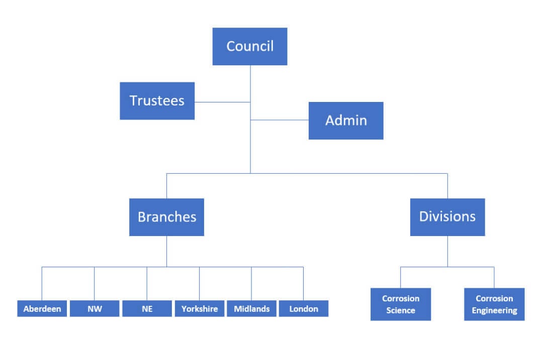
The Council of the Institute of Corrosion
Our Council is like the Board of Directors of a large company. It is the Institute’s highest decision-making body, and every branch, division, and committee report to the Council. The Council is made up of the following members:
There are five trustees, and these form the ‘committee’ that oversees the routine running of the Institute between Council meetings. The trustees are the following Institute of Corrosion members:
The President
The Vice President
The Immediate Past President
The Honorary Secretary
The Honorary Treasurer
Our Head Office
Our head office, Corrosion House, is where all the admin work is conducted. Located in Northampton, the staff of three here work tirelessly to ensure that every t is crossed and i dotted across every aspect of the running of ICorr.
Beneath the Council, our structure allows information and operations to flow freely in all directions as follows:
The Branches of the Institute of Corrosion
The six regional branches let us reach deep into the heart of the corrosion community in the UK:
Aberdeen
London
Midlands
Northeast
Northwest
Yorkshire
The work they do and the networking opportunities they present to our members is vital. They have a great deal of autonomy, and run various events that include:
Seminars/webinars
Technical workshops
Social events
Every event and interaction within our branches is a networking opportunity, and a chance for members to learn and share ideas, experience, and best practices.
The Two Divisions of the Institute of Corrosion
Though depicted on the organisational structure chart as a single leg of our not-for-profit organisation, the two divisions really stretch across every part of ICorr. Their reach is in everything we do:
The Corrosion Engineering Division (CED)
Made up of five Working Groups, the CED also runs a Working Day and Symposium. The Working Groups are:
Nuclear Corrosion
Coatings
Cathodic Protection
All Energy
Corrosion in Concrete
The Corrosion Science Division
This division consists of representatives from the corrosion research community – primarily academia and research – and runs the annual Corrosion Science Symposium.
Young ICorr
While the experience of senior corrosion professionals is crucial in our industry and to the Institute, equally vital are the younger engineers and scientists who are entering and progressing in their careers in corrosion prevention.
Young ICorr is a vibrant and forward-looking group, through which many initiatives and early-career networks are formed, and from which we believe corrosion industry leaders of tomorrow will develop.
The Committees of the Institute of Corrosion
Finally, to the committees ─ without which the Institute of Corrosion could not function effectively. This is where much of the day-to-day work is managed. These teams meet up when needed, collaborate with other teams, and ensure that actions agreed are carried out.
The Awards Committee
Responsible for overseeing the portfolio of ICorr awards, and for the nomination of ICorr members for external awards. The recognition of excellence both internally and externally helps us to demonstrate the authority with which the Institute operates and the professionalism, knowledge, and expertise of our members.
The Building Management Committee
This committee is responsible for the maintenance and upkeep of our Head Office, Corrosion House in Northampton. They may not get their hands dirty with building work, but without them we might not have a home!
The Course Approval Board
The education of the corrosion community, at whatever stage of their individual careers, is crucial to the future of our industry, and, indeed, the future of our world – when corrosion control is ignored it can be catastrophic.
The Digital Strategy Committee
In our digital world, it is easier to connect, build networks, and share expertise than ever before. However, to do this effectively, it is essential to develop and follow strategy that aligns with the goals of the Institute. This is the remit of the Digital Strategy Committee.
The Membership Development Committee
The real strength of the Institute lies in its membership. The broader and deeper our membership is, the more we can offer and provide to them and the global corrosion community.
The Membership Development Committee is responsible for initiatives to increase our membership and highlight the benefits of membership.
The Professional Assessment Committee (PAC)
While the Membership Development Committee is responsible for driving membership applications, it is the PAC that handles membership and upgrade applications.
Correx Limited
Though we are a not-for-profit organisation, our commercial activities are key to our present and future sustainability. However, it is also crucial that we keep the operation of these at arm’s length. To ensure this is the case, we registered Correx Limited in 2003.
It is Correx that organises all of our commercial activities, and especially the administration of ICATS (Industrial Coating Applicators Training Scheme). ICATS is mandated by the Highways Agency and Network Rail for all coating applicators – and it is also a requirement for many other major structure owners including Oil Companies, Power Generators, and Infrastructure Owners.
In future articles, we plan to explore each element of the organisational structure of the Institute of Corrosion, to help all our members and the wider corrosion community to have a greater understanding of all the moving parts of the Institute and the tremendous amount of work that goes on behind the scenes. If you’re interested in getting involved in any of these activities, please get in touch with us!
The questions in this issue feature, the possible corrosion impact of oxygen, and use of different zinc-based coatings.
Question:
In an oil and gas development I am working on in the Far East, a concern has been raised about possible corrosion impact due to excess oxygen. The current plan for gas lifting wells is to use N2 with 96% purity, with the remaining 4% oxygen. With operating pressures of 2300 – 2800 psig (at 1 mmscfd), this means that there will be a high level of O2 seen in the produced fluids. The production casing is carbon steel (CS) and the tubing material, 13 Cr steel is used in two wells, and carbon steel used in one well. The N2 gas will be delivered to well head platform via 850 m of flexible flowline (plastic material designed for high pressure) and then injected down the annulus. The production from the wells flows to a FPSO for further processing.
We are looking to reduce oxygen in gas phase and currently thinking of using an oxygen scavenger. Appreciate your expertise to advise on how these issues can be overcome. CM
Answer:
With this application there are two different issues to discuss.
• 13CR corrosion in the tubing
With 4% oxygen in the injected gas at these high pressures it would be expected that the dissolved oxygen in the production stream would be very high, and that the aqueous phase to be fully saturated with oxygen. In theory, some oxygen is helpful for CRAs (Corrosion Resistant Alloys) as they can form a protective film with oxygen. This complex film formed contains the structure, -Cr-O-Cr – O-Cr-, with chromium surrounded also by water ligands, and this makes the excellent protective film on the metal surface. However, it has been known (especially in the presence of high chlorides with 13Cr) that high oxygen may lead to deep pitting. This is because chloride gets inserted in this chromium oxide complex and weakens it, which can lead to the rupture of the protective film. The corrosive fluids with oxygen can now contact the metal surface and lead to serious pitting corrosion. As noted, a small amount of oxygen is a good thing for CRAs, but higher levels may lead to failures.
• Carbon steel corrosion
Carbon steel tubing in the annulus and one of the wells may undergo heavy corrosion in the presence of oxygen. Oxygen generally is more corrosive than CO2 or H2S. The by-products (magnetite or hematite) from oxygen corrosion are not protective, so will not protect the steel under any circumstances. This is a situation (very high oxygen) where oxygen scavengers are not cost effective and are also very difficult to apply to a gas stream. Although not an easy option, inhibition can be used in some instances for oxygen corrosion, but It is important that the product be selected in the correct manner as not all inhibitors are effective against oxygen corrosion.
In this situation, the best overall solution would be to reconsider the gas used for the gas lift system and use a source that does not contain oxygen. This would solve the issue in both annulus and tubing, although if other corrosive species are present CO2 /H2S this would need to be assessed as well. Even with dry gas if there is fluid in the annulus of the well, the gas will get re-saturated with water during injection, so would not be a solution. If this is not an option, inhibition could be considered, although it is very important to use a good oxygen corrosion inhibitor and inject so it that it will inhibit both the annulus and production fluids. The product (s) need to selected correctly to account for the oxygen present, and the application needs to ensure that distribution in the gas and water phase in the product fluids occurs.
George Winning, Clariant Oil Services UK Ltd Question:
“Zinc-based coatings can provide long term corrosion protection for steel substrates. What is the difference in zinc thickness needed between galvanising, thermal metal spray, and zinc-rich coatings, to give maximum life to first maintenance in different exposure conditions, and what are the cost implications?” K McKee
Answer:
A good question but the answer is probably more complex than you might expect!
Firstly, the corrosion protection system selected needs to be able to achieve the required corrosion protection in the given service environment. On this basis, zinc rich paints alone would not be widely used for primary corrosion protection, and where they are used, it is probably limited to category C1 (low corrosivity environments) as described in ISO 9223. There is no specific guidance on the coating thickness for a zinc rich paint, although they are typically used for touch-up and repair of small areas of damage to a galvanized coating where a coating thickness of 100 microns is required. The cost of application may be less than alternative systems but then the level of protection provided is limited with more frequent maintenance schedules being required!
Batch hot dip galvanizing (e.g. galvanizing after fabrication) is the most commonly used means of applying a zinc coating for corrosion protection. The process is conducted to BS EN ISO 1461 with the coating thickness requirement varying from 45-85 microns dependent upon steel section thickness, although thicker coatings up to 140 microns may be specified if steelwork is grit blasted before hot dip galvanizing. For most atmospheric applications an 85 micron galvanized coating will typically achieve a coating life of 60 years in many atmospheric environments, although thicker coatings may be specified for more corrosive environments. The cost for hot dip galvanizing is charged on a pounds per tonne basis using the as-galvanized weight of the article. Costs may vary according to the size and weight of an article and the volume of work to be processed.
Thermal spraying tends to be conducted on large solid structures which are literally too big to hot dip galvanize and while a zinc coating can be applied, often a zinc-aluminium or aluminium coating is preferred. The process is covered by BS EN ISO 2063 and typically a minimum coating thickness of 100 microns or more would be specified, although this may be increased significantly for corrosive environments. A final point to note is that due to a thermal sprayed coating not being fully dense, an organic sealant often has to be applied. The cost of thermal spraying is typically greater than that for hot dip galvanizing, in part due to the need for steelwork to be grit blasted, the application of an organic sealant, and
the limited number of coating applicators.
Dr Desmond Makepeace, Technical Executive, Galvanizers Association
We use cookies to optimize our website and our service.
Functional
Always active
The technical storage or access is strictly necessary for the legitimate purpose of enabling the use of a specific service explicitly requested by the subscriber or user, or for the sole purpose of carrying out the transmission of a communication over an electronic communications network.
Preferences
The technical storage or access is necessary for the legitimate purpose of storing preferences that are not requested by the subscriber or user.
Statistics
The technical storage or access that is used exclusively for statistical purposes.The technical storage or access that is used exclusively for anonymous statistical purposes. Without a subpoena, voluntary compliance on the part of your Internet Service Provider, or additional records from a third party, information stored or retrieved for this purpose alone cannot usually be used to identify you.
Marketing
The technical storage or access is required to create user profiles to send advertising, or to track the user on a website or across several websites for similar marketing purposes.