













CP in Concrete – An Explanation of the Exponential Ageing Model

CP in Concrete – An Explanation of the Exponential Ageing Model

George Sergi, FICorr, Technical Director at Vector Corrosion Technologies Ltd

Meet The Author

George Sergi is the technical director at Vector Corrosion Technologies Ltd. He has long been involved in research and development for concrete durability consulting and problem-solving in the construction and concrete repair industry and is skilled in materials science, highways, bridge inspection, and steel-reinforced concrete repair and protection. George holds a PhD from Aston University for his work on the corrosion of steel in concrete. He was previously the head of corrosion at the Building Research Establishment (BRE), technical manager at FOSROC Constructive Solutions and lead bridge consultant for Birmingham City Laboratories.

The following summary is intended to provide specific clarification on the use of the Exponential Ageing Model for CP in Concrete, as referred to by C M Stone and G K Glass in their article “A critical assessment of the half-life Ageing term and failure to predict future galvanic anode behaviour”, Corrosion Management, Issue 187 [1].

Regarding long-term monitoring data from a hybrid anode installation at Whiteadder Bridge [1] they argued that:

  1. The observed current decay did not follow an exponential relationship over the full-service life.
  2. A constant residual current dominated long-term
  3. Early high current output was governed by curing or resistivity changes in the activator rather than anode ageing.
  4. Changes in steel passivity, rather than anode condition, governed long-term current trends [3].

These interpretations are examined below in the context of electrochemical fundamentals, field data from multiple installations, and laboratory evidence.

An Explanation of the Pre-Passivation Regime Within the Ageing Factor (AF) Model

The (AF) model does not assume indefinite exponential decay. It describes the pre-passivation regime, during which:

  • Corrosion products are at least partially transported away from the zinc/activator
  • The anode remains electrochemically
  • The zinc surface area decreases progressively due to
  • Both geometric modelling and long-term field data consistently show that, during this regime, current output halves at approximately constant time intervals. This behaviour has been observed across multiple installations and for:
    • Different anode geometries
    • Varying exposure conditions

For the Whiteadder Bridge data [1], the first 8–9 years of operation exhibited a clear exponential decline, yielding an AF of approximately 3 years, which confirms the existence of an exponential ageing regime.

Transition to Passivation Stage

The deviation from exponential decay at later ages, resulting in an asymptotic or quasi-constant current, is not evidence against the AF concept and instead reflects a transition to a passivation-controlled regime, in which:

  • A continuous corrosion product layer forms at the zinc/activator
  • The zinc surface becomes effectively
  • Current output is limited to a low level governed by oxide

This behaviour is well known in electrochemistry and is analogous to passive steel behaviour. The same transition has been observed in:

  • Laboratory depolarisation and potential-shift studies [4]
  • Non-alkali-activated anodes
  • Overdriven alkali-activated anodes

Steel Passivation – Effect on Anode Current

It has been proposed [3] that decreasing current is driven by increasing steel passivity. This interpretation is electrochemically inconsistent. As steel becomes more passive, its potential shifts in the positive direction. For a galvanic system, this increases the driving voltage between zinc and steel, which would, all else being equal, tend to increase rather than decrease anode current.

Observed reductions in current therefore, cannot be attributed to steel passivation alone and must originate primarily from changes at the anode interface.

Post Passivation Behaviour

Once passivation occurs, current output becomes largely independent of remaining zinc mass or theoretical surface area, and exponential modelling is no longer applicable. The AF model is therefore not intended to describe post-passivation behaviour, a limitation that is now explicitly recognised.

Activator Resistivity Changes

It has been suggested that early current decay resulted from curing or resistivity changes in the activator putty. For this mechanism to account for the observed reduction, the resistivity of the activator would need to increase by several orders of magnitude over a relatively short period.

Such behaviour is inconsistent with:

  • Known curing behaviour of cementitious or polymeric activators
  • Independent laboratory measurements of activator resistivity
  • Observations from alkali-activated systems where similar activators exhibit stable resistivity but very different ageing behaviour

By contrast, the formation of zinc oxide/hydroxide corrosion layers several millimetres thick provides a physically plausible, experimentally supported explanation for the observed current limitation.

Zinc Potential Evolution

Potentiodynamic scans and long-term exposure tests demonstrate that:

  • Aged anodes show substantially less negative potentials ( −750 mV).
  • New alkali-activated zinc anodes exhibit corrosion potentials <−1100 mV vs Ag/AgCl.
  • Non-alkali-activated anodes can shift to even more positive values within a short period.

This progressive ennoblement of the zinc potential directly reduces the galvanic driving force and is consistent with corrosion-product-induced passivation and anode-controlled ageing. Some independent studies by BAM/ibac [4] corroborate this behaviour.

Implications for Future CP Design and Interpretation

The apparent contradiction between exponential decay and long-term constant current disappears once ageing is recognised as a multi-regime process:

  1. Geometry-controlled exponential decay (AF regime)
  2. Resistance-influenced decay due to gradual pore blocking
  3. Passivation-controlled residual current

Well-designed alkali-activated anodes delay the onset of Regime 3 above beyond the design life, allowing the AF model to be used

reliably for long-term prediction. Note. Systems that enter Regime 3 early must instead be designed based on the residual current.

Galvanic Anode Monitoring – Design Considerations

An explanation of the Exponential Ageing Model


Discussion

  • Exponential decay of galvanic anode current has been experimentally observed and theoretically justified.
  • Any deviation from exponential behaviour typically results from passivation and should not be interpreted as failure of the ageing model.
  • Differences between systems arise from activator chemistry, anode geometry, and degree of over-driving.
  • The AF remains a valid and necessary design parameter within its defined

Galvanic Anode Monitoring – Lessons Learnt

  • Current Density halves at regular time intervals found to be 3-15 years, depending on anode activator and type and degree of anode overdriving, a term described as “Ageing Factor”.
  • Exponential decline of current density up to the Design Limit is consistent with “Half-Life” principle.
  • Humidity and particularly temperature, modify current output

Conclusions and General Guidance

The normal service life of installed galvanic anodes is expected to be at least 15 years and possibly 20-30 years.

  • Current output of galvanic anodes is sustained for many years with a gradual exponential drop at a measured rate (Ageing Factor – AF).
  • The Ageing Factor can be built into the design of the anode system to predict minimum service life.
  • Enough knowledge has now been gained about anode behaviour over time to allow design to any required level of steel

References

  1. M. Stone & G.K. Glass “A critical assessment of the half-life Ageing term and failure to predict future galvanic anode behaviour” Corrosion Management, Issue 187, pp. 35-39, September/October 2025.
  2. Stone, W Carr & A Roberts “Analysis of the half-life “ageing-constant” theory for galvanic anodes: Analysing the model’s predictive power for CPT anodes” MATEC Web of Conferences 409, 02001 (2025) https://doi.org/10.1051/matecconf/202540902001.
  3. Dodds, C. Christodoulou, C.I. Goodier, Hybrid anode concrete corrosion protection – independent study, Proceedings of the Institution of Civil Engineers: Construction Materials, Vol. 171, 4, pp. 149-160, Aug. 1918.
  4. Federal Institute for Materials Research and Testing (BAM) and ibac – Institute for Building Materials Research at RWTH Aachen University “Performance of galvanic and hybrid anode systems for reinforced concrete structures” Final Report on Industrielle Gemeinschaftsforschung (IGF) Project no. 20408 N, 30/11/2022
  5. https://www.icorr.org/wp-content/uploads/2021/06/2021-03-30-ICorr-Aberdeen-Event-ICorr-Aberdeen-Presentation-30-03-21-Dr-George-Sergi-Vector-Corrosion.pdf
  •  


Fellow’s Corner

Fellow’s Corner

Overcoming Plant Isolation Issues within Cathodic Protection Design

Dr Ahmed Mahgoub, FICorr

Dr Ahmed Mahgoub is cathodic protection subject matter expert for Saudi Arabian Oil Company (Saudi Aramco) in Dhahran, Saudi Arabia. He has more than 19 years of experience in the consulting, engineering, constructing and commissioning of different cathodic protection structures. He is a an AMPP CP Specialist, ICorr CP specialist, Fellow of ICorr, ICorr CPGB Member and AMPP Snr. Corrosion Technologist.

Introduction

Cathodic protection (CP), when applied properly, is an effective means to prevent corrosion of underground plant piping. For many underground applications, such as pipelines, CP system design is relatively straightforward. Plant and facility environments, however, are not simple applications. Plants have congested underground piping systems such as process drains and other utilities in a tightly spaced footprint. The presence of copper grounding systems, foundations with reinforcing steel embedded in concrete, conduit, utility piping and structural pilings (either bare or concrete with reinforcing steel) can greatly complicate the task of designing a pipe CP system.

For simple plant facilities, it is possible to isolate the piping and utilise a conventional galvanic corrosion prevention system. This works only if the plant piping is electrically isolated from other underground structures for the life of the facility. For most plant and facility applications, it is not practical to isolate the piping from the grounding system for the life of the facility. In these cases, an impressed current cathodic protection (ICCP) anode system is the only alternative as a galvanic system does not normally have sufficient capacity to overcome plant earth connections. This paper represents the linear mixed metal oxide (MMO) anodes, which in suitable conditions can be an optimal method of providing adequate CP protection criteria as specified in [1-4] to the piping network in crowded areas of oil and gas plants.There are two conventional approaches to cathodically protecting underground plant piping using impressed current anodes – deep vertical anode bed and shallow / distributed anode bed. However, there are three principal industry challenges to consider for any CP system within a plant and described as shortages in utilising a conventional ICCP system.

  • First is the current distribution issue due to highly congested underground environment that is common to most plants.
  • The second critical factor is isolation in the presence of a pervasive copper grounding network, often applied for safety reasons to protect rotating equipment and security fences.
  • Third is the probability of DC interference due to stray currents from multiple sources.
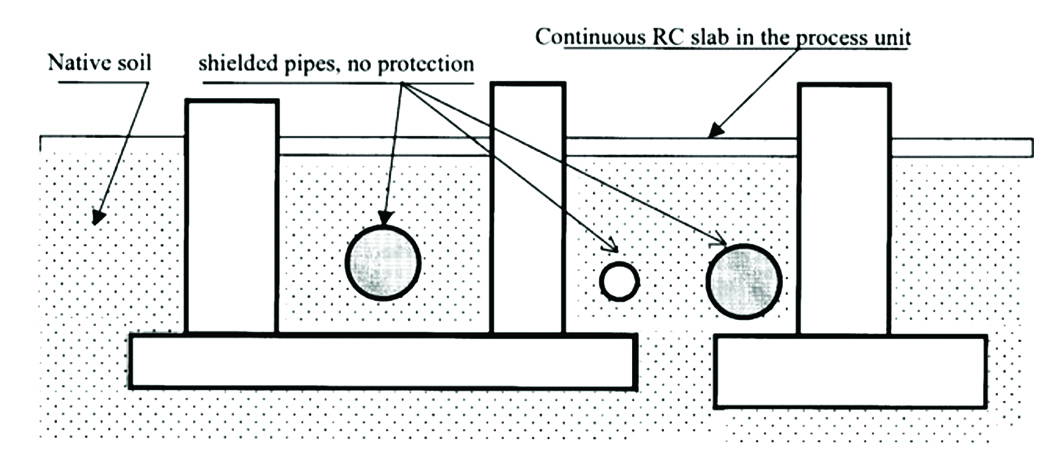
Figure1: A Typical Process Piping Layout Where Reinforced Concrete Foundations are Restricting The Flow of Protective Current.

MMO System

The linear MMO Anode is a long-line, flexible, cable-like anode, which is placed in continuous close proximity to (typically 0.5m to 1m from) the piping network. In conditions of similar backfill/resistivity, uniform distribution of CP current is therefore achieved on applications where many conventional anodes ground beds do not work or would cause excessive interference. In contrast to conventional anode ground beds CP systems, Linear MMO Anode is placed in the ground parallel and in close proximity to the plant piping to be protected and provides uniform distribution of protective current to the entire steel surface as demonstrated in various studies [4-9], thereby maintaining the steel-to-soil “instant-off” potential in the required protection criteria.
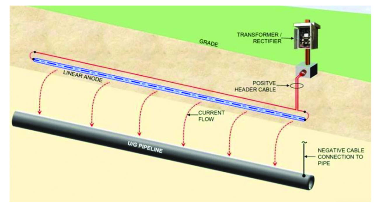


Figure 2: UG Pipeline CP System with Single Linear Anode Layout.

Backfilled Linear Anode

The MMO based anode represents the second generation of backfilled linear anodes. The platinum based catalytic anodes were quickly replaced with MMO based wire anodes as they were more cost effective, less prone to failure, allowed for a longer anode system life and a larger range of current outputs, and provided a far more robust material.
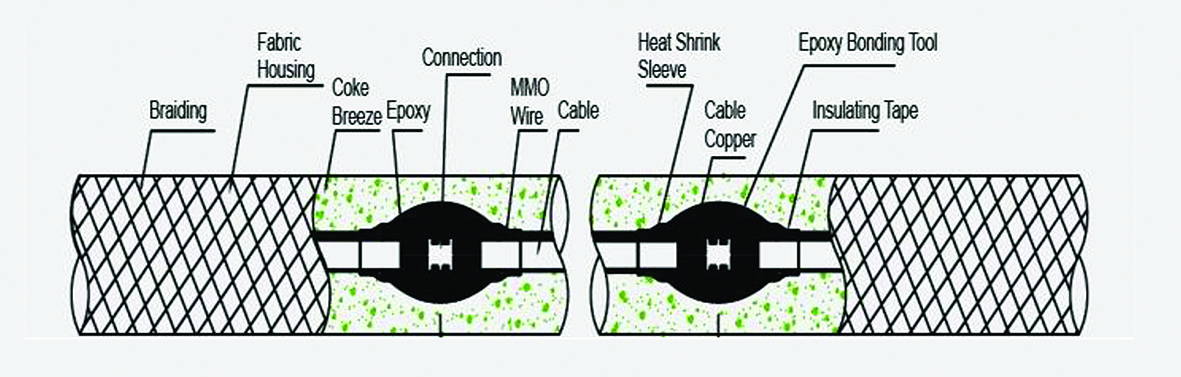
Figure3: MMO Linear Anode Composition.

Below are the key elements that contribute to the MMO linear anode composition,

  • Core, is crafted from high-quality titanium wire. This core is meticulously coated with a catalyst blend derived from Mixed Metal Oxides, predominantly featuring Iridium and Tantalum
  • MMO Coating, on one hand incorporates an electrocatalytic conductive element, which acts as a catalyst to drive the essential reactions for current generation. On the other, it embeds bulk oxides that serve as a protective shield, ensuring the substrate material remains resistant to corrosion.
  • Acid Resistance Fabric, this fabric is designed to provide an additional layer of protection against acidic environments. Its unique composition ensures that the MMO linear anode remains safeguarded from potential corrosive effects of acids, thus enhancing its longevity.
  • Protective Braid, surrounding the anode is a protective braid which offers mechanical protection. This robust braid ensures that the anode is shielded from external wear and tear, making it more durable and resilient to external forces.
  • Coke Breeze is a common backfill material for ICCP systems. It not only enhances the conductivity of the anode but also aids in distributing the current This ensures efficient operation and reduces potential hot spots.

The MMO linear anode functions as a distributed system including an infinite number of continuously spaced anodes. This system offers the optimal technical CP solution while minimising the required current output as detailed below:

  • Electrical isolation is not necessary, Because the MMO linear anodec is closely located next to the piping being protected, electrical isolation as illustrated in [4] is not a significant concern. The anode is “closely coupled” to the piping and operates with a very low anode gradient that minimises any losses to nearby structures including grounding equipment.
  • Maintains uniform current distribution by positioning the anode parallel and in very close proximity to the piping being protected, the linear anode CP system design eliminates any requirement for supplemental anodes to address areas where remote anodes may be shielded after the CP system is commissioned. Wherever the piping goes, the linear anode follows in the same trench. This also makes it very easy to adapt the design during piping revisions that may change the piping system routing as the plant construction Sufficient care must be taken during its installation of course.
  • Elimination of stray current risks, close proximity to the piping being protected significantly limits current losses to other structures and virtually eliminates shielding and stray current This also significantly reduces the total current requirements for the system, reducing the rectifier requirements.
  • Access restrictions, the MMO linear anode is installed in very close proximity to the piping that is to be protected. This minimises the risk of third-party damage and reduces trenching required for buried cable and drilling required for distributed anodes. If installed in conjunction with the piping, the anode can be placed in the same trench as the piping affording the anode protection by the piping itself from external damage. This is a very cost-effective CP installation when installed concurrently with the piping and to correct spacing.
  • Ease of installation, when installed alongside the piping during pipelay a matter of laying the anode cable in the trench with no further drilling is needed.

Case Study

  • This section outlines the proposed CP system by linear MMO anodes for new 8” & 6” underground Header and branch underground piping’s network in Saudia The total length of the gas grid distribution piping network in this instance is 4900m and the piping will be protected by a permanent (ICCP) system for a lifetime of (25 years) according to project specifications by applying a new CP system of 25V/15A rating.
  • The MMO Linear Anodes comprise a continuous MMO/Ti wire with copper cable packaged in fabric jacket fulfilled with calcinated coke installed parallel to the pipelines in the same trenches by maintaining a minimum distance of 0.5-0.8m from pipeline.
  • A header cable is attached at the factory via a high-pressure crimp connector to ensure a low resistance That connection is then sealed in a splice kit with epoxy resin to prevent water intrusion.
  • Finally, the header cable to anode feeder cable connection is performed on site as per the manufacture specification and standard
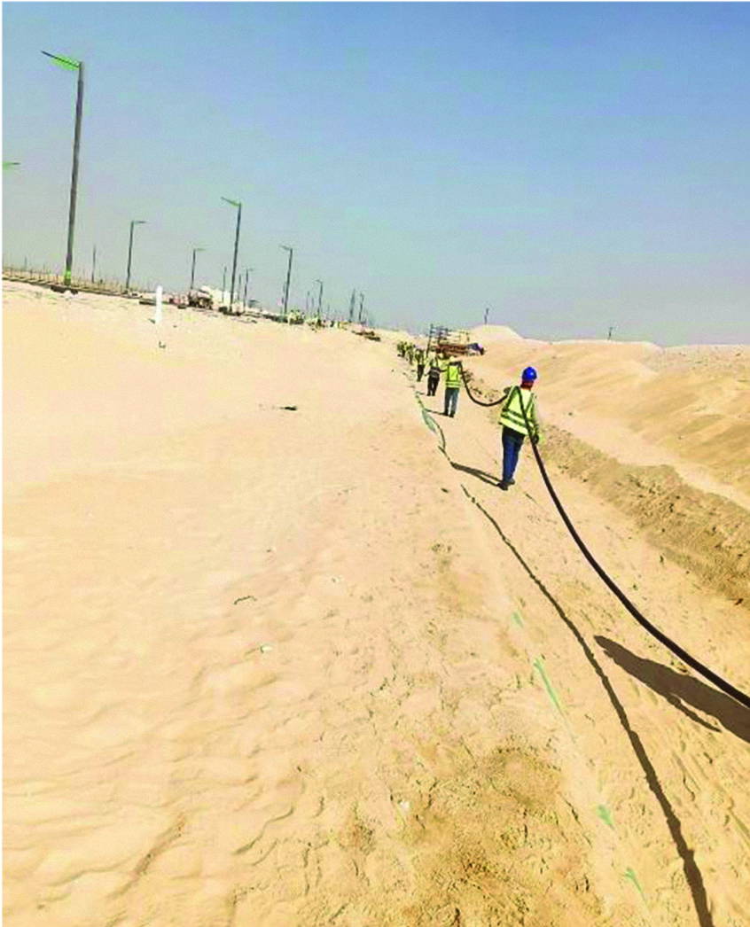
Figure 4: Installation of the MMO Linear Anode.
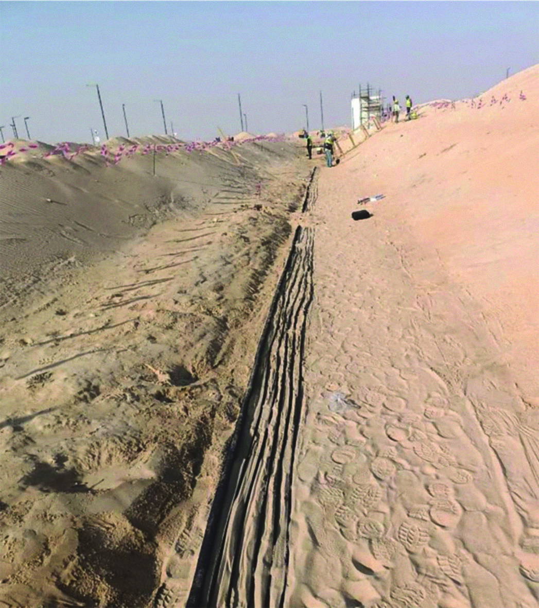
Figure 5: Installation of CP Cables in The Same Trench of the MMO Linear Anode.

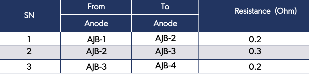
The CP system must then be examined to confirm the proper installation of all components. It is crucial to verify the connections and continuity of the positive anode cables. Resistance measurement between various anode feeders is required to ensure electrical continuity, as well as between different main positive cables. The resistance reading should be less than 1 ohm. Sample results of the continuity test are illustrated in the tables below.

Table 1. Anode Feeders Continuity Test Sample.

Table 2. Main Positive Cables Continuity Test Sample
During CP commissioning activities any temporary sacrificial anodes must be disconnected and the piping given 96 hours to depolarise before measuring the native potentials which were found in this instance to lay in the range -410 to -635mV copper/copper sulphate (CSE) with an average of -550mV. Thereafter the permanent CP was commissioned and energised and the piping allowed to polarise for 48 hours at 4.5Volt/2.2Amp setting. ON ‘pipe to soil’ potentials were measured at all test stations and the Instant-Off pipe to soil potentials were then measured at DC coupon test stations. Both ON & Instant-Off potentials did meet the required CP criteria as specified in Saudia Aramco COMPANY specifications. The records of Native, ON and the Instant-Off pipe to soil potentials are illustrated in the tables below.

Table 3. Native, ON and the Instant-Off Pipe to Soil Potentials at DC Coupon Test Stations.
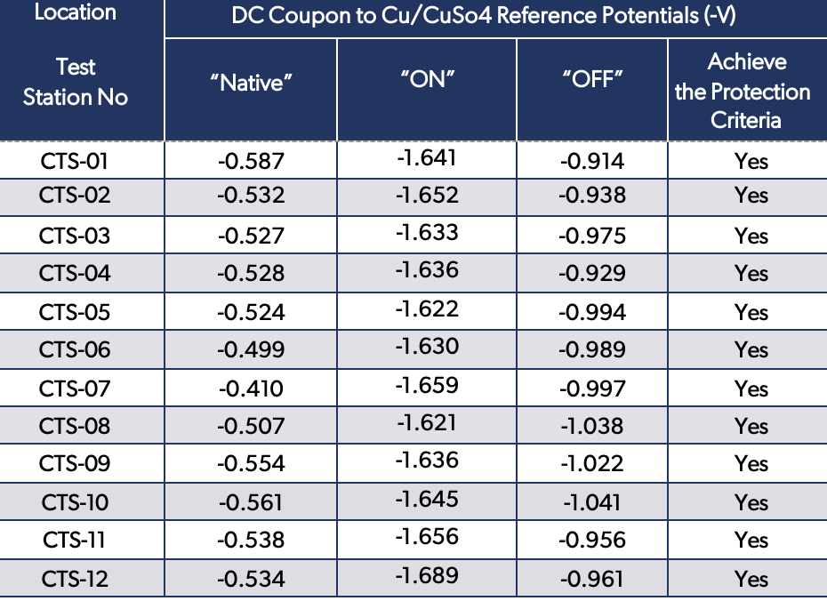
Table 4. Native and ON Pipe to Soil Potentials at Test Stations

Summary

Process equipment reinforced concrete foundations and electrical plant grounding are usually an integral part of the plant. Shielding of underground piping network in congested oil and gas plants is one of the major problems when CP is applied for its protection from external corrosion. Not only is a significant amount of protective current consumed by these elements, but also, they restrict the flow of protective current to the intended structures from a conventional, distributed or remote ground bed. CP of plant piping where current leakage and stray current caused by reinforcement concrete foundations and grounding rods are a real problem.

MMO Linear anodes are a modern solution that can simply be laid alongside a new pipeline and current distribution and polarisation formation are normally better in case of anodes installed close to the pipeline, MMO linear anode is an effective method to protect the plant piping against soil side corrosion.

The utilisation of MMO linear anode for plant piping protection will also lead to a substantial decrease in project installation and maintenance expenses, as well as improved performance in comparison to the traditional method of CP distributed anode. In this particular case study, the approach of Linear MMO anode to be utilised for plant piping protection resulted in revising the initial plan to drill and install 50 distributed anodes. As such, significant cost savings were realised resulting in approximately 3850 meters of cable trenching and 50 drill anodes with total depth of 250 meters were eliminated in addition to avoiding the need for anode bed replacement for an extended period, ranging from 25 to 40+ years, can result in significant cost savings in terms of capital cost.

References

  1. ISO 15589-1, Petroleum, petrochemical and natural gas industries — cathodic protection of pipeline systems, Part 1: On-land pipelines, ISO, 2015.
  2. NACE/AMPP SP0169, Control of external corrosion on underground or submerged metallic piping systems, NACE International, Houston, 2013.
  3. EN 14505, Cathodic protection of complex structures, BSI 2005
  4. NACE/AMPP SP0286, Electrical isolation of cathodically protected pipelines, NACE International, Houston, 2002
  1. A Nordquist, “Cathodic protection design considerations in congested area facilities,” Paper No. 10900, in Proceedings of the NACE/AMPP Corrosion Conference & Expo 2018, NACE/AMPP, Houston, TX
  2. A W Al-Mithin, “Effectiveness of cathodic protection system for buried flow lines near gathering centres using continuous linear anodes,” Paper No. 0001530, in Proceedings of the NACE/AMPP Corrosion Conference & Expo 2012, NACE/AMPP, Houston, TX
  3. M Attarchi, “Simulation of linear anode-pipe cathodic protection system: primary and secondary current and potential distribution analysis,” NACE/AMPP Journal of Science and Engineering, 75(9), 1128–1135.
  4. Z Chaudhary, “Cathodic protection of piping network in congested area of a petrochemical plant,” Paper 05050, in Proceedings of the NACE/AMPP Corrosion Conference & Expo 2005, NACE/AMPP, Houston, TX.
  5. T Huck, “Linear anode for pipeline rehabilitation – thirty years later,” Paper No. 19993, in Proceedings of the 18th Middle East Corrosion Conference and Exhibition (MECC) 2023.
  6. A H Mohammad, “Problems associated with remote anode beds in very low resistivity soil for protection of piping networks in congested areas of a petrochemical complex,” Paper No. 03713, in Proceedings of the NACE/AMPP Corrosion Conference & Expo 2003, NACE/AMPP, Houston, TX.


Fellow’s Corner – Nov/ Dec 25

Fellow’s Corner – Nov/ Dec 25

This series of articles is intended to highlight industry-wide engineering experience, guidance and focussed advice to practising technologists. It is written by ICorr Fellows who have made significant contributions to the field of Corrosion Management.

Can Corrosion Be a Help Rather Than a Hindrance?

Gareth Hinds, PhD, FICorr, EFC President, ICorr Past President

Meet the Author

Gareth Hinds

Dr Gareth Hinds is Senior NPL Fellow and Fellow of the Institute of Corrosion. He is Science Area Leader in the Electrochemistry Group at the National Physical Laboratory in Teddington, United Kingdom. His primary expertise is in the development of novel in situ diagnostic techniques and standard test methods for assessment of corrosion and material degradation in energy applications. Gareth is a Fellow of the Royal Academy of Engineering and holds visiting professorships at UCL, the University of Strathclyde, Harbin Institute of Technology and the Institute of Corrosion Science & Technology, Guangzhou. He is the author of over 200 publications and is currently
President of the European Federation of Corrosion.

Corrosion is often viewed in a negative light. It can lead to premature failure of metallic components and infrastructure, with significant economic, environmental and safety-related consequences. As ICorr members, we’re only too familiar with the need to combat this ever-present threat. However, in the right circumstances corrosion can also be exploited as a force for good! This Fellows Corner article takes a closer look at some examples.

Galvanic Cells

Corrosion is an electrochemical phenomenon involving the transfer of electrons and ions between conducting surfaces in contact with an electrolyte. It can therefore be harnessed in a controlled way to produce electrical power. When a battery is discharging, it acts as a galvanic cell, analogous to galvanic corrosion of two dissimilar metals, with the negative electrode acting as the anode and the positive electrode as the cathode. Control is achieved by isolating the electrodes from each other using an insulating porous separator, typically a polymer or ceramic. When the battery terminals are connected to an electrical load, usable DC current will flow. The first battery was the Voltaic pile [1], which was invented by Alessandro Volta in 1800. This consisted of alternating discs of zinc and copper separated by strips of cloth soaked in brine. The anodic reaction was corrosion of zinc, with hydrogen evolution on copper as the cathodic reaction. The Voltaic pile played a central role in the discovery of water electrolysis by Carlisle and Nicholson [2] in 1800 (only a few months after its invention) and in the isolation of chemical elements (Na, K, Ca, B, Ba, Sr and Mg) by Humphry Davy [3] in the early 1800s.

Figure 1: Statue of Alessandro Volta In His Birthplace of Como, Italy, Featuring His Voltaic Pile [1], The Forerunner of The Modern Battery.

Please Note: this article considers only spontaneous (galvanic) reactions in order to be consistent with real corrosion processes. Electrolytic processes are excluded. The scope is also restricted to electrochemical corrosion of metals to keep things relatively simple.

Volta mistakenly thought that the operation of his battery was a consequence of static electricity and seems to have used it mainly to deliver electric shocks to unsuspecting volunteers. It wasn’t until the 1830s that Michael Faraday demonstrated the electrochemical basis of its operation. Nevertheless, Volta’s invention and its subsequent evolution formed the basis for electricity generation throughout most of the 19th century, until the discovery of the electrical generator in 1870.

Today, batteries are playing a vital role in decarbonisation of our energy system, most notably in electric vehicles and grid storage. Unlike most forms of corrosion, the electrochemical reactions in some batteries are reversible. Examples include lithium-ion and lead-acid batteries, which can be charged and discharged many times over their lifetime. If only all corrosion reactions behaved in the same way!

Another well-established electrochemical technology that operates under the same galvanic principle is the use of sacrificial anodes to prevent corrosion. Anodic dissolution of the more active metal (usually an alloy of magnesium, aluminium or zinc) allows the more noble metal (normally steel) to remain protected under conditions in which it would otherwise freely corrode. This is the basis for cathodic protection of a wide range of infrastructure, including pipelines, storage tanks, marine structures and reinforced concrete.

Like batteries, cathodic protection has a long history, dating back to 1824 when Humphry Davy used iron anodes to protect copper sheathing on the hull of HMS Samarang [4]. While this did prove highly effective in preventing the copper from corroding, it was soon observed that marine biofouling had increased dramatically, as copper ions were no longer being released in sufficient quantity to kill the microorganisms. Since biofouling creates drag that slows down the ship, the Royal Navy decided that on balance it was better just to let the copper corrode, highlighting yet another beneficial effect of corrosion!

Surface Modification

Corrosion of a metal surface can be advantageous if it leads to the formation of a highly protective film. This is the case with weathering steels used in the construction industry. When exposed to atmospheric conditions, these steels initially corrode like mild steel but over time a dense, stable, patina forms that effectively prevents any further corrosion and is self-healing if damaged. This leads to huge cost savings in that no painting is required and maintenance costs are minimal.

Weathering steel was introduced in 1933 by US Steel as a high strength material for coal wagons in the railway industry. The steel composition had been developed by trial and error over many decades and it was entirely by chance that its corrosion resistant properties emerged. It was trademarked as ‘Corten’ steel – ‘Cor’ for ‘corrosion resistance’ and ‘ten’ for ‘tensile strength’. The mechanism behind the establishment of a corrosion-resistant patina is still not fully understood but it’s clear that wetting and drying cycles are required and that copper is the most important alloying element. Of course, care should be taken not to use weathering steels in environments where a protective patina does not form. This will often be the case if the steel remains continuously wet or is exposed to high levels of chloride. Similarly, service experience shows that the patina forms more effectively in industrial and urban environments than in rural environments where atmospheric corrosion rates are much lower.

The most famous example of the use of weathering steels in the UK is probably the Angel of the North statue in Gateshead, which is seen by an estimated 33 million people every year due to its elevated position close to major North-East road and rail arteries [5]. Erected in February 1998, it was designed by sculptor Anthony Gormley and stands 20m tall with a wingspan of 54m. Most of Gormley’s work is in bronze, but in this case weathering steel had to be used to provide sufficient strength to withstand periods of high wind.

Figure 2: The Angel of The North Statue In Gateshead [5] Was Constructed From Weathering Steel Due To Its Combination of Mechanical Strength And Corrosion Resistance. Image Source: Saw2th CC BY SA 2.0.

The widespread use of aluminium, stainless steel and other corrosion resistant alloys also depends on the formation and self-healing properties of a protective oxide layer in a range of aqueous environments. Here, the balance between metal ion dissolution and oxide formation governs the level of protection offered by the passive film. Passivation is a direct consequence of corrosion; without this critical phenomenon many engineering alloys would be completely useless!

Another advantageous surface modification that can arise from corrosion is crack tip blunting. Stress corrosion cracking, where stress and a corrosive environment combine with a susceptible microstructure to generate fracture well below the yield stress of the material, is a common failure mechanism in many industrial applications. Initiation and propagation of stress corrosion cracks depends on the presence of stress raisers such as corrosion pits and crack tips. However, when the corrosion rate is sufficiently high, dissolution of the metal can round off the sharp edges of the crack tip, significantly reducing the stress concentration factor and arresting crack growth. This can be useful as a means of mitigating crack development, but a balance is clearly needed as if the corrosion rate is too high other issues will emerge.

Selective Material Removal

Chemical etching is a well-established manufacturing process whereby corrosion is actively employed to achieve selective removal of material from a metallic component to realise the desired final shape. A masking material is often used to protect areas of the surface where material removal is not desired.

Very precise control of component shape can be achieved through the application of a photo-resistive material, a light-sensitive polymer that is stable in the etchant, to the entire surface. Prior to the etching step, exposure to light through a patterned mask can either weaken or strengthen the photoresist material, allowing removal of selected areas with an appropriate solvent.

The etching process can be used to manufacture highly intricate and complex shapes for a range of important applications, including aerospace, automotive, medical, microelectronics and energy conversion and storage devices. This avoids the issues of burrs and residual stresses that can be introduced by mechanical milling.

The earliest known application of chemical etching comes from ancient Egypt, where it was used to inscribe jewellery with hieroglyphs and images of deities. This was carried out in a relatively crude manner using rudimentary acids and abrasion. The process became more sophisticated over time with the invention of acid baths in the 15th century and modern etchants developed during the Industrial Revolution.

In metallography, acid etching is a well-established technique for microstructural characterisation of metals and alloys. A common etchant is nitric acid, which tends to remove material in the grain boundaries more rapidly than the grains themselves, making the microstructure easier to see in an optical microscope. This allows visualisation of grain size, phase segregation and inclusions that can be linked to the properties of the material.

Aesthetics

The products of corrosion can display a wide range of pleasing colours due to the optical properties of metal oxides. Energy is absorbed and released by electrons as they transition between energy states in the metal atom when interacting with light. Every metal oxide exhibits a distinctive colour that depends on the metal, its oxidation state and the surrounding chemical environment. For example, iron oxides are mostly reddish-brown, cobalt oxide is blue and magnesium oxide is white.

The green-blue patina that forms over time when copper is exposed to atmospheric corrosion is copper carbonate. This patina is not only visually attractive but also highly protective of the underlying metal. Famous landmarks incorporating this feature include the Statue of Liberty, the Kremlin Palace and Berlin Cathedral. However, one of the major drawbacks of the use of copper in less high-profile structures is that it is often targeted by thieves for its high resale value. In February 2017 for example, St Peter’s Church in Kirby Bellars near Melton Mowbray, Leicestershire, faced a £70k repair bill after the theft of a large amount of copper from its roof [6]. Sadly, this is becoming an increasingly common issue, particularly in rural communities.

Figure 3: The Striking Colour of The Domes on Berlin Cathedral is A Result of Prolonged Atmospheric Corrosion of Copper.

Pigments are products of corrosion that exhibit colour and have been used in art since antiquity. Use of pigments dates back 400,000 years to early humans who used yellow ochre (hydrous iron oxide) for ritual painting. Red ochre (anhydrous iron oxide) features heavily in cave paintings from the Neolithic period, such as those found at Lascaux in France. Early pigments used by artists were based on minerals and clays, although these have now been largely supplanted by modern synthetic variants.

Corrosion can even be an art form in itself. Jean Kittel, a researcher at IFP Energie Nouvelles in Lyon, France, has created a collection of artwork based on corroded metal, including copper, bronze and iron [7]. This impressive work was highlighted recently when two of his pieces were selected as prizes for a scavenger hunt that took place to mark 2025 World Corrosion Awareness Day [8].

Figure 4: Artwork By Jean Kittel [7] In Which A Corroded Polishing Disc is Printed With Prussian Blue And Sanguine Inks. Image Provided By Jean Kittel.

Material Functionality

The presence of a corrosion reaction can add considerable value if it leads to an improvement in the functionality of a material. Often the corrosion process is intentionally incorporated into the material or component design for maximum benefit.

Biodegradable medical implants are designed to be dissolved completely via corrosion once their primary function has been completed, thereby avoiding the need for a second surgery to remove them. The majority of these are organic or polymer-based but this is not possible for orthopaedic implants, where metals are required due to their higher load-bearing capacity.

In contrast to their well-established corrosion-resistant counterparts, such as titanium and cobalt-based alloys, metallic biodegradable implants are typically based on magnesium and zinc alloys that are much more susceptible to corrosion in the environment of the human body [9]. This is still an emerging area, with further research required to optimise design and implementation.

Just a small amount of corrosion of the steel reinforcement bars (rebars) in reinforced concrete enhances adherence of the concrete to the steel [10]. This is due to a combination of increased surface area and the expansion of the iron oxide to fill voids between the steel and the concrete. Of course, all benefit is lost at higher corrosion rates as the expansion of the oxide then creates stresses that lead to debonding and cracking of the concrete.

In alkaline water electrolysis, stainless steel catalysts can become activated by corrosion, leading to higher rates of hydrogen production [11]. Selective etching of the surface, particularly of chromium, leads to the formation of a nanostructured, porous surface layer that is rich in catalytically-active nickel and iron oxides. Again, caution is required as there is a trade-off between activity and stability that can be challenging to manage.

More generally, corrosion accelerates nutrient cycling in ecosystems by breaking down minerals in rocks and making them available to living organisms. So it’s also a vital component in keeping us alive and healthy.

Summary

It’s clear that there are many positive aspects of corrosion that, when used and controlled in the right way, are highly beneficial in a range of important applications. As always, there’s a balance, and care needs to be taken that any downsides are well mitigated.

However, there’s one additional major benefit that shouldn’t be overlooked. Let’s not forget that corrosion keeps most people reading this in business! Metals will always revert to their oxides if we do not intervene judiciously. For this I guess we ought to be thankful!

References

[1] A. Volta, On the Electricity of the Pile, Philosophical Transactions of the Royal Society, September 1800.

[2] T. Smolinka et al., Chapter 4 – The History of water electrolysis from its beginnings to the present, Electrochemical Power Sources: Fundamentals, Systems, and Applications 83, 2022.

[3] J.L. Marshall, Humphry Davy and the Voltaic Pile, Chem 13 News Magazine, April 2019.

[4] H. Davy, Additional experiments and observations on the application of electrical combinations to the preservation of the copper sheathing of ships and to other purposes, Philosophical Transactions of the Royal Society, January 1824.

[5] P.J. Nicholson, Antony Gormley, The Angel of the North, 1998, Occupational Medicine 68, 352, 2018.

[6] https://www.meltontimes.co.uk/news/crime/raiders-make-off-with-copper-sheeting-from-kirby-bellars-church-roof-2105331.

[7] https://www.jean-kittel-estampes.com/.

[8] https://www.ampp.org/blogs/
webmasternaceorg/2025/04/14/ampp-joins-global-effort-of-corrosion-prevention.

[9] B. Xia, Y. Liu, Y. Xing, Z. Shi, X. Pan, Biodegradable medical implants: reshaping future medical practice, Advanced Science 12, e08014, 2025.

[10] A. Ouglova et al., The influence of crrosion on bond properties between concrete and reinforcement in concrete structures, Materials and Structures 41, 969, 2007.

[11] Y. Zuo et al., Stainless steel activation for efficient alkaline oxygen evolution in advanced electrolyzers, Advanced Materials 36, 2312071, 2024.

Fellow’s Corner

Fellow’s Corner

This series of articles is intended to highlight industry-wide engineering experience, guidance and focussed advice to practising technologists. It is written by ICorr Fellows  who have made significant contributions to the field of Corrosion Management.

B S Wyatt is an ICorr Past President, a member of the CP Governing Board (CPGB) and CEOCOR Immediate Past President. Brian is an independent Consulting Corrosion Engineer, a CP specialist in applications for steel in soils, waters and concrete. Experienced in design, performance assessment, detailed survey techniques and remedial work for:

• Onshore buried and offshore pipelines
• Offshore new build and retrofit CP for oil, gas and renewables structures
• Internal and external surfaces
• Coastal and port/harbour structures
• Steel in concrete for bridges, tunnels and buildings.

Brian is an expert witness in multiple sectors of CP, he has carried out technical consulting and project management of large and complex CP systems. He is a UK Nominated Expert by BSI for CEN/TC219 and ISO TC156/WG10. He is active in the ICorr Training, Examination and Certification of CP personnel in accordance with BS EN ISO 15257. Brian has competence Certification to ISO 15257 Level 4 in all 4 Sectors: Buried, Steel in Concrete, Marine and Internals and Certification to Level 5.

The Role of an Expert Witness

Introduction

I have been requested by the Editor to submit a paper on the role of an expert witness. For reasons I will explain below, this is quite a difficult task, but I will do my best within the necessary confidentiality of cases in which I have been appointed to this role.

There are several other Fellows of ICorr working as expert witnesses. Some, like me, only occasionally undertake such work, others have chosen this activity as a major part of their fee earning activities. One is resident in and very active in the USA.

I explain below, how I assess approaches from legal teams and determine if I think I am suitable for, and if I am prepared to act as an expert, in the case in which they are involved.

For those readers who have not experienced technical or construction disputes, and whose exposure to the actions of expert witnesses may be limited to newspaper reports of criticisms of expert witnesses, or the reported inadequate understanding of expert witness testimony by the courts, for example in UK medical negligence cases, or to fictional US cases in criminal cases, please be ready to be disabused.

General Rules

Firstly, the rules for expert witnesses are quite different in the UK and the USA. I have taken guidance in the summary below from the Global Arbitration Review1 and from Bond Salon2.

England and Wales have established the Civil Procedure Rules: Rules and Directions, Part 35 (CPR Part 35)3, which set out the requirements for expert evidence, specifically requiring that an expert witness has an overriding duty to the court to be independent and impartial. As a result, ‘experts should constantly remind themselves through the litigation process that they are not part of the Claimant’s or Defendant’s “team” with their role being the securing and maximising, or avoiding or minimising, a claim for damages. Although experts always owe a duty to exercise reasonable skill and care to those instructing them, and to comply with any relevant professional code, as CPR 35.3 expressly states, the experts have at all times, an overriding duty to help the court on matters within their expertise. That they have a particular expertise and the court and parties do not (save in some professional negligence claims) mean that significant reliance may be placed on their analysis, which must be objective and non-partisan if a just outcome is to be achieved in the litigation.4

From Ref 1 ‘The UK judiciary has made criticisms of expert evidence in, for example, ICI v. Merit,[15] Riva v. Fosters,[16] Energy Solutions v. NDA[17] and Russell and Anor v. Stone,[18] which highlighted that a ‘hired gun’ who pretends to be independent is of little help to a tribunal and may damage the position of the instructing party. It may cause the parties to incur higher expenses in the whole proceedings, prevent any settlements or render the expert evidence of little assistance to the tribunal. An expert must maintain objectivity and independence. The English courts have given many judgments regarding the bias of experts; for instance, in Jones v. Kaney,[19] the Supreme Court of the United Kingdom removed the immunity of an expert witness from lawsuits for negligence.’

Expert witness reports are required to contain a ‘statement of truth’ which would typically be in the following form:

‘I confirm that I have made clear which facts and matters referred to in this report are within my own knowledge and which are not. Those that are within my own knowledge I confirm to be true.

The opinions I have expressed represent my true and complete professional opinions on the matters to which they refer.

I understand that proceedings for contempt of court may be brought against anyone who makes, or causes to be made, a false statement in a document verified by a statement of truth without an honest belief in its truth.’

In one case in which I was involved, I was asked to attend chambers of the leading barrister who would be putting the case for the party who had appointed me. One of the expert witnesses for the other party had made claims that I considered to be spurious and that were directly contradicted by a published document that the expert had previously written; I had identified this in my opinion report. The barrister [many of whom can be quite robust] described the expert as a ‘man of straw’ and said that he would ‘enjoy picking the wings off this fly’. The case was settled before the hearing.

In the United States, Federal Rules of Evidence (US FRE) Article VII sets out the requirements governing the rules for opinion and expert testimony, which are less prescriptive. The conduct of expert witnesses, and their overriding duty to serve and assist the court, is not established under the US FRE. I am advised by my expert fellow colleague that there are differing rules in different states.

Corrosion expert witnesses in the USA and elsewhere, must be experienced and have specialized knowledge or skills to offer unbiased opinions to help attorneys, judges, mediators and juries understand complex corrosion issues.  The Daubert Standard5  is now the law in federal court and in other courts over half of the states.   Related to Daubert, attorneys may question expert witnesses if they are knowledgeable in the Scientific Principle6 7, which is intended to eliminate bias.

In the USA, a corrosion expert – before testifying – must stipulate that their scientific or engineering knowledge will assist the court or tribunal understand the facts in issue.  These responsibilities should ensure that expert witnesses are able to play a crucial role in ensuring fair and informed decision making in legal cases.

In international disputes the contract terms will normally have defined the rules and jurisdiction under which any dispute will be subject to arbitration or settlement, if the latter, often by an expert tribunal. In all in which I have been involved the CPR Part 35.3 rules have been applied either formally as these rules by name or by direct copying of their requirements. In large international construction contracts, the parties may have agreed to use a particular form of arbitration to address any disputes; one such is prepared by the United Nations Commission on International Trade Law (UNCITRAL).

With all this being said, the reality is that once appointed, all the information related to the case that the expert requires to properly execute his or her work comes from the instructing party’s legal team, and it is normal for there to be meetings with the legal team and with the instructing party’s personnel who have information on the matters in dispute. Eventually, some of these personnel with intimate knowledge of the matters in dispute will present their own witness statements. During the process there will be a need for legal advice for the expert in respect of procedures for the hearings in court or before a tribunal. Draft expert reports may be commented on by the instructing party’s legal team and barrister(s); however, at no time should the expert be prepared to receive or act on instruction to change his or her expressed opinion. During a long preparation for a hearing there is a risk that a ‘team spirit’ is developed, particularly if there are multiple experts with interlocking expertise; hence the emphasis in Ref. 4 above: ‘Experts should constantly remind themselves through the litigation process that they are not part of the claimant’s or defendant’s “team”, with their role being the securing and maximising, or avoiding or minimising, a claim for damages.’

In all of the expert witness cases in which I have been involved, before tribunals or an arbitration expert, the evidence and the outcome, where it has become known to me, have been strictly confidential. The details remain so. Therefore, my description of the process is necessarily restricted. In cases that are heard in the Technology and Construction Courts  , the CPR Part 35 rules apply, however, the judgements are published.

In my experience a typical process has been:

1. The Initial Contact

A phone call or e-mail, out of the blue, often from a legal professional, but occasionally from a technical or scientific professional with expertise in a related or unrelated field, typically asking guarded

questions regarding expertise, availability and, very soon, regarding conflicts of interests.

This might proceed to the exchange of limited documents regarding the dispute and the parties, under a confidentiality agreement. It is at this point where, historically, I have sometimes declined to be involved, either because I am not comfortable acting for the ‘instructing party’, or I think from the limited information available the instructing party’s case is likely ill-founded or indefensible, or I consider that my expertise is not appropriate for the scope of the case. Where I can, I have pointed the enquirer towards people, often also Fellows of ICorr, who I think are either more competent than I am in that field or more likely to wish to work on the particular case.

If I am interested and available and the key issues are within my expertise and still under confidentiality agreements, there are exchanges of more technical details, sometimes preliminary timetables and suggested fees. It is at this stage, before any appointment that I detail, that I describe, I hope honestly and self-critically, my relevant technical strengths and weaknesses.

2. The Appointment

Typically, quite quickly, a draft engagement letter will be sent by the instructing legal team, detailing who they act for, who are the parties to the dispute, and the jurisdiction which will hear the details of the dispute by way of the claims and counter claims, which may be an Arbitration Board, Tribunal or a Court. The engagement letter may also detail other experts already appointed, providing other expertise [e.g., coating, testing, etc.], and it may outline in more detail the provisional timetable. The legal team will have obtained approval from the court or tribunal for the appointment of experts and their anticipated costs.

The engagement letter will require confidentiality and ‘legal privilege’; likely all documents to and from the expert will be marked ‘Privileged and Confidential – prepared for use in XYZ proceedings. It will require disclosure of any conflicts of interest [which will likely exclude the expert from the proceedings] and either directly or indirectly, compliance with the CPR Part 35 rules. In all such cases, the workload and the attention to detail required are abnormal. I have had multiple boxes of small print A5 files of evidence arrive by courier on a Friday evening with a requirement for initial comments the following Monday morning. Every word on the page of an expert witness report, or ppt. presentation to be used in evidence should be 100% accurate and impossible to be misinterpreted.

In one of the largest cases in which I was involved, I gave evidence for a day and a half and ‘suffered interrogation’ from the most aggressive barrister I have ever met. My expert technical report, which I had worked on for many, many hours, was hardly addressed. I was advised afterwards that he could find nothing of substance in it to challenge, and his challenges were primarily of me and my expertise. Before this long tribunal hearing, I was grateful to have taken part in some expert training in how to deal with such questioning and how to react in front of the tribunal.

3. The Work Process

The overall Work scope typically falls into 4 stages:

• Outline and Scheduling

• Assessment

• Review and Final presentation

• Proceedings

Outline and Scheduling

Initially the expert will be presented with the claims and counter claims from the parties in the dispute, the claimant and the respondent.

At a relatively early stage in the process a draft timetable will be published advising when expert reports are to be submitted, if an ‘experts meeting’ is required, and when court or tribunal hearings are planned. At around the same time a list of experts will be exchanged between the claimant and respondent. This may result in an

assessment of particular areas of expertise being brought to bear on the evidence by one party and the need for the other party to strengthen the expert witness team in this area. It is critical at this time for any appointed experts to be realistic in respect of the limits of their expertise and experience. I have advised a legal team that a particular expert in the team for the other party had expertise beyond mine in what could be a relevant sector, and that the legal team should consider adding another expert in order to competently address matters within this sector.

Assessment

Then the real work begins, with a thorough review of all the available evidence, possibly requesting additional information if any is available, or suggesting additional testing in order to better inform if there is any ‘fault’ or to better determine the impact of any such fault on the required performance of the asset at the core of the dispute. All such requests and any additional data or site visits and their outcomes must be openly shared between all of the parties.

Depending upon the complexity of the dispute there may be many hundreds of relevant documents. Different legal firms have different methods of presenting these to experts, some largely in hard copy bound documents, some in well-constructed and easy to access electronic systems and some in less easy to use systems.

Review and Final presentation

I have been involved in a number of cases as an expert where I have been required to prepare power point presentations for the tribunal or arbitration board. The purpose is to present an accurate summary of the previously prepared expert opinion report which can be presented before the tribunal. Draft expert reports or opinions are presented, and questions can be submitted between claimant and respondent, in order to seek clarity.

It may also be required that experts appointed by both claimant and respondent meet, in what is termed an ‘experts meeting’ with the intention of determining what, if any, matters in dispute can be agreed between the experts, and thus to be removed from,  or closed off in, the later revisions of the expert opinion reports and the eventual proceedings. The intention is to simplify and reduce the costs of the process, whilst retaining the key issues in the dispute to be assessed by the court or tribunal without the distraction of matters that can be agreed. These meetings between experts are normally ‘without prejudice’ and the legal teams for the claimant and respondent may determine not to accept removing the agreed items from the dispute.

Proceedings

Experts should be prepared for the parties to a dispute to reach a compromise agreement in the weeks or even days before the planned court or tribunal hearing. This has happened to me in several cases.In one particularly complex overseas case I had been to the job site for some weeks, collecting more information and, in parallel, preparing the final version of my expert opinion report, along with a power point presentation to be used in the hearing. On the day before my planned time before the tribunal, for which I considered I was well prepared, I was phoned and told to go home; the matter had been settled. At the time I was disappointed, thinking that part of my work was incomplete; on reflection on this and other disputes settled before the planned court or tribunal hearing, the appropriate conclusion is that the expert has, to the best of his or her’s ability, clarified the matters in dispute for the parties and the court/tribunal in order to facilitate an agreed settlement. Job done.

Personal Experiences

Over the years I have been appointed as an expert in cases related to CP failures on sheet steel piles in seawater and saline infills, hot oil pipelines, to district heating schemes, to pipelines in swamps with disputed field joint coating quality, a buried pipeline with disputed field joint coating quality and disputed CP system adequacy, offshore wind farm monopile foundations, ship hull coatings and related CP performance and others. The Figures to the right are NOT from expert witness cases in which I have been appointed [due to confidentiality issues] but examples of some of the sectors in which I work.

External Corrosion on Buried Gas Transmission Pipeline:

The Thames Barrier London (not a dispute but a success where independent experts were assessing the corrosion protection performance)

A project on which I was involved for many hours alongside another Past President of ICorr, David Deacon. David was a respected coating expert, but not a believer in CP. He was persuaded of the efficacy of CP on this project, which was well designed by our mutual expert predecessors and we had the pleasure of assessing their success:

In my non-dispute related experience, often with colleagues, I have investigated and assisted in developing and executing remedies for failed corrosion protection schemes [CP, coatings and other related matters] or as independent technical expert(s) advising employers in complex CP related schemes being designed and executed by others. Much of the same rigour and obligations mandated to be applied in technical or construction dispute resolution outlined above are applicable to these activities. From my personal experience, expert witness work can be significantly disruptive to other professional activities and to personal life, but I have enjoyed the intellectual challenge of attempting to make the evidence to the court, or tribunal, complete, clear, detailed and as far as possible, difficult for a barrister whose role is to demolish my evidence or credibility to the benefit of his or her client, to misinterpret. In all of this, the evidence is not for the barristers, it is for the judge or tribunal panel and is intended to make what can be quite complex and subtle technical matters clear to all.

References

1. https://globalarbitrationreview.com/guide/the-guide-construction-arbitration-archived/fifth-edition/article/expert-evidence-in-construction-disputes-expert-witness-perspective .

2. https://www.bondsolon.com/expert-witness/expert-witness-training/

3. https://www.justice.gov.uk/courts/procedure-rules/civil/rules/part35

Quotation from a Bond Salon briefing note regarding a 2022 dispute.

4. https://www.bailii.org/ew/cases/EWHC/KB/2022/2648.html

5. https://www.law.cornell.edu/wex/daubert_standard.

6. https://legalclarity.org/what-is-an-example-of-the-frye-standard-in-court/

7. Scientific principles give foundation to definitive expert opinions evaluating hypotheses for causation and feasibility for extraordinary claims.

8. https://www.judiciary.uk/courts-and-tribunals/high-court/technology-and-construction-court/


Fellow’s Corner

Fellow’s Corner

This series of articles is intended to highlight industry-wide engineering experience, guidance and focused advice to practising technologists. It is written by ICorr Fellows who have made significant contributions to the field of corrosion management.

1824 and All That – A Celebration of The Bicentenaries of CP and PC

Paul Lambert, Head of Materials and Corrosion Technology at Mottmac

On January 22, 1824, the Philosophical Transactions of the Royal Society in London received a paper entitled ‘On the corrosion of copper sheeting by sea water, and on methods of preventing this effect, and on their application to ships of war and other ships’. The author was Sir Humphry Davy, and it describes a study with his colleague Michael Faraday into what we now know as cathodic protection, which celebrates its 200-year anniversary in 2024. It was many years later before the true value of cathodic protection was recognised for the protection of buried and submerged steel structures. It was championed by the formation of the Texas-based Mid-Continent Cathodic Protection Association in 1938, which by 1943 had evolved into the National Association of Corrosion Engineers (now AMPP) in the USA.

But that is only half the tale. On October 21st 1824, a bricklayer in Leeds patented a new formulation of hydraulic binder for mortar and concrete which he called Portland cement due to its similarity to the popular structural stone, especially when mixed with beach sand. Portland cement eventually dominated the manufacture of all concrete worldwide.

200 years on, the long-term durability limitations of Portland cement concrete are regularly made good by the application of cathodic protection, making 2024 a very important year for those involved in reinforced concrete and its remediation.

Happy 200th birthday to Cathodic Protection and Portland Cement.

Sir Humphry Davy of Penzance (1778 – 1829).

Photo courtesy of Pen with Local History Group

https://corrosion-doctors.org/Corrosion-History/CP-History.htm

Fellow’s Corner – Douglas Mills

Fellow’s Corner – Douglas Mills

Douglas Mills undertook PhD research on anti-corrosive coatings at Cambridge University and has worked on and off in this field since. After spells at the BNF Metals Technology Centre and the Nuclear Power Company, in recent times he has worked in academia, and apart from teaching materials, he has continued to conduct and supervise research in the field of electrochemical methods for application to coatings, particularly studying and developing the electrochemical noise method. He was for fifteen years the Technical Secretary of the Institute of Corrosion and is also involved in standards development.

Douglas Now Lays Down His Story:
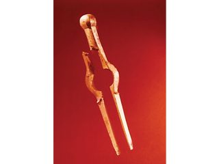
I have had an interest in archaeological corrosion ever since I did work in this area many years ago at the British Non-Ferrous (BNF) Metals Technology Centre in Wantage. This was “An examination of artefacts brought up from the seabed after 262 years”. In 1707 several ships of the line from a fleet of twenty one under the command of Sir Cloudesley Shovell, hit the rocks of the Scilly Isles during a fierce storm and sank. This included the flagship HMS Association. In 1969 a team of divers under the overall control of Roland Morris recovered many artefacts. The BNF was given a Royal Society grant to examine these, and it fell to me to carry out much of the work. Conducting chemical analysis as well as metallographic studies, enabled us to find out (and comment on) the type of corrosion, the nature of the corrosion product and the extent of corrosion. Also, the composition and metallurgical structure of the metals/alloys were compared with similar alloys used today. The items included, brass dividers a bronze cutlass handle lead musket balls and silver pieces of eight as well as lead pipe, pewter platters, a copper spike, and (bronze) ship’s bells. (There was also bronze cannon although my work did not extend to examination of these).

I did this work under the direction of Hector Campbell. one time editor of the British Corrosion Journal, with whom the 70page report was written.

Much later I became involved with the Maritime Museum in Gdansk.

I was able to pass this report over to Kasia (their corrosion expert). The museum had bits from two ships (“Copper Ship” and “Solen”) which sank in the Baltic a similar length of time ago). On the metallurgical side, the composition of many of the alloys used was surprisingly close to what might be used today and many were also reasonably pure for example.

Lead musket balls: afforded an interesting comparison with musket balls from the Swedish warship Wasa, visible in its entirety in museum in Stockholm, which sank some 60 years earlier in the Harbour there. This was possible because the original size and weight of musket balls was known and hence (assuming linear) we could work out the corrosion rate and compare them. What was found was that sea water conditions in the Scilly Isles (clean and turbulent) afforded a less aggressive environment than Stockholm harbour (polluted) led to about half the rate of corrosion.

Brass dividers: These had undergone hardly any corrosion; the points made of iron had rusted away completely (bimetallic corrosion), and maybe they provided galvanic protection in the early stages. But it was the fact that the brass was single phase and contained some arsenic (a useful inhibitor of dezincification) that probably saved the dividers.

• Bells: one from HMS Romney (probably!) and one from HMS Association. These, despite similar composition (two phase: one copper rich and one tin rich), had corroded in quite different ways with one phase being attacked in one bell and the other phase in the other. Interesting polarisation / potentiostatic work done in the lab revealed that the two bells had probably been subjected to different environmental conditions – half of one bell having been buried in mud while the other bell was freely exposed to sea water.

Pieces of eight: The interest here was in developing a more efficient cleaning method compared with the normal one which was lengthy and removed significant amount of silver, achieved partly by using an electrochemical method.

Protective Coatings and Electrochemical
Assessment Methods

This kind of research i.e., towards understanding long term corrosion and its prevention, has relevance today to both the storage of nuclear waste and conservation. The afore mentioned Kasia and I have collaborated in developing an electrochemical assessment method for corrosion protective coatings. The specific interest here is in how do you keep things in the museum environment from continuing to corrode? But there are also ancient artefacts outside like statues. The most common approach is application of

thin, invisible organic coatings. Getting the right coating is quite a challenge as the appearance must not to be altered. The Museum at Gdansk had a bell and bowls which had been protected by these thin transparent coatings. How do you assess such coatings? One approach is to use Electrochemical measurement techniques like DC resistance or Electrochemical Noise. Some recent work done in Northampton University tested four such coatings and concluded that Paraloid (conservation grade acrylic lacquer) coatings were the best. But only if you applied two thin (typically
10-20mm) coats.

Other Discoveries
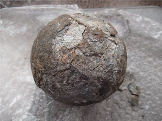
Moving back to the discovery phase on a more local level i.e., people discovering archaeological items in the earth, the father of a friend found a large cannon ball in the south of England which I was invited to have a look at. It had a thickish layer on the outside and this interestingly was not iron based but contained large amounts of lead.
The inside of the cannon ball was very likely cast iron, based on its hardness and the calculation of density (between 6.8 gm/cc and 7.5 gm/cc. Cast Iron has a density of 7.3 gm/cc.)
Outer lead casing – why was the outer lead put on? Was it a corrosion protective layer? What was the environment that caused the more noble lead to corrode so extensively? (apparently faster than the musket balls in the sea, as all the lead exterior was destroyed). Was it pure lead or some lead alloy which was more corrodible? Maybe the smoother lead surface assisted in the firing (that seems very plausible). One possibility is that it was never used in anger but was lost while being transported. Such cannon balls were used on big ships (even as early as the Mary Rose, Henry VIII’s flagship, from the early 16tH century) So it could have been travelling between the Arsenal and Portsmouth when it “fell off a cart!”
In summary lots of questions raised and only speculative answers! This is the fascination with any investigation of archaeological corrosion. It leaves plenty of room for the Imagination!

References:
1. H. S. Campbell and D. J. Mills Marine Treasure Trove – A Metallurgical Examination Metallurgist & Materials Technologist October 551 (1977).
2. Mills, D.J.; Schaefer, K.; Wityk, T. In-Situ Evaluation of the Protectivity of Coatings Applied to Metal Cultural Artefacts using Non-Destructive Electrochemical Measurements. Corros. Mater. Degrad. 2021, 2, 120–132. https://doi.org/10.3390/cmd2010007.
3. Schaefer, K.; Mills, D.J. The application of organic coatings in conservation of archaeological objects excavated from the sea. Progress in Organic Coatings Volume 102, Part A, January 2017, Pages 99-106.

Brass dividers
(almost no corrosion).

Lead musket balls with varying rates of corrosion according to submersion condition.

Pieces of eight after electrochemical cleaning.

Cannon Ball (weight 4 kG (9 lbs) Diameter 11cm (density 6.8-7.5) with Corrosion Product about 1-2 mm thick.