This series of articles is intended to highlight industry-wide engineering experience, guidance, and focussed advice to practising technologists. It is written by ICorr Fellows who have made significant contributions to the field of corrosion management. This issue features an introduction to intumescent coatings, by Brian Goldie.
Passive Fire Protection – Intumescent coatings
Today most buildings and structures have some degree of fire protection in order to protect lives, delay possible structural collapse allowing for evacuation, provide areas of temporary refuge in the case of fire, and ensure the integrity of escape routes, by preventing or delaying the escalation of a fire and protecting high-value assets.
There are two basic types of fire protection: active and passive. Active fire protection includes alarms and detection systems, sprinklers and water deluge systems, firefighting equipment and foam and powder extinguishers. Passive fire protection involves materials such as concrete, mineral fibre boards, vermiculite, cements, and intumescent coatings. This article will describe how intumescent coatings can achieve passive fire protection in many structure types including offshore platforms or floating facilities, such as FPSOs and FLNGs, and commercial buildings.
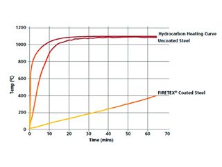
Intumescent coatings have been used to protect the steelwork in buildings and other structures from fire for approximately 40 years. These coatings work by swelling up in the event of fire and physically creating a barrier between the steel and the fire for as much as 4 hours in some cases. Steel begins to lose its structural strength at about 400 C, and these coatings can delay the time it takes to reach this temperature (Figure 1). Intumescents are often referred to as thin- film or thick-film coatings.
Thin-film intumescents are typically single component solvent or waterbased products, and have dry film thicknesses (DFTs) of less than 5 millimetres. In the last few years new technologies, such as multi-component methacrylate, or “hybrid” products, have been brought to the market, offering specific advantages over the traditional products.
Thick-film coatings are typically solvent-free, epoxy-based with DFTs of up to 25 millimetres.
The acceptance and use of intumescent coatings increased dramatically in Europe in the 1980s as the major oil companies learned of their ability to protect structural steel from the extreme heat caused by hydrocarbon fires, including jet fires caused by leaking hydrocarbons. Also, exposed steel was used more prevalently in the design of commercial structures and high-rise buildings, increasing the use of thin-film intumescents, which looked more like conventional paint and therefore could meet the aesthetic requirements of architects.
How Do Intumescent Coatings Work?
Intumescent coatings react to fire by expanding to form a carbon “char” with low thermal conductivity, which essentially forms an insulating layer reducing the rate of heat transfer and extending the time necessary to reach the critical failure temperature of the underlying steel.
It’s a complex chemistry incorporating the organic binder resin (coating) — typically an epoxy (hydrocarbon fire) or acrylic (cellulosic fire), and an acid catalyst, for example ammonium polyphosphate, which decomposes to yield a mineral acid. This acid reacts with a carbonific source, for example, pentaerythritol, to produce a carbon char. A spumific (foam-producing) agent, such as melamine, reacts with the acid source and decomposes, evolving into an inert gas which then expands the char. These are the basic reactions taking place, although more complex interactions also occur. Reinforcing mesh can be used to support the formed char.
Cellulosic vs. Hydrocarbon Fires
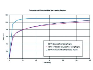
A cellulosic fire has a fuel source composed mainly of cellulose — for example, wood, cardboard, or paper. Hydrocarbon fires are fuelled by hydrocarbon compounds and ignite and grow exceedingly fast, achieving high temperature almost immediately after ignition, greater than 1,000C in less than five minutes (Figure 2). Cellulosic fires are slower to reach maximum temperature but may eventually reach or surpass the temperature of a hydrocarbon fire.
A hydrocarbon pool fire is defined as a turbulent diffusion fire burning above a horizontal pool of vapourising hydrocarbon fuel, where the fuel has zero or low initial momentum. A jet fire is a turbulent diffusion fire resulting from the combustion of a fuel continuously released with high pressure.
Testing Intumescent Coatings
No two fires are the same. The conditions depend on the type and quantity of fuel, the availability of oxygen and ambient conditions. For reproducible product testing. “standardised” fires have been defined, for example, BS 476 (parts 20 and 21) “Fire tests on building materials and structures” and EN 13381 (part 8), “Test methods for determining the contribution to the fire resistance of structural members” describe how intumescent coatings are tested with cellulosic fire exposure. Performance depends on coating thicknesses, the types of steel section, I-section, hollow section, and the section orientation, i.e., beam or column.
Other test standards include UL 1709, “Rapid Rise Fire Tests of Protection Materials for Structural Steel” for hydrocarbon fire exposure, ISO 22899-1, “Determination of the resistance to jet fires of passive fire protection materials”. Different standards apply to marine applications. It is not possible to test every variation, so the test results are analysed to produce an assessment of performance.
Ensuring Durability
To protect steel in a fire, a coating must be resistant to the environment and be intact at the time of the fire. Poor durability can lead to ineffective fire protection resulting in structural failure during a fire and expensive restoration afterwards. Poor durability can also lead to corrosion of the substrate, compromising structural integrity. To ensure durability of intumescent coatings the key ingredients — ammonium polyphosphate, melamine and pentaerythritol — are all sensitive to moisture, and must be formulated carefully.
Different resins are used to prepare intumescent coatings for different applications. Water-based acrylic materials are formulated for use in mainly dry, internal locations. Solvent- based acrylic materials are used to formulate intumescent coatings for use in internal or sheltered external locations.
Solvent-based or solvent-free epoxy materials are used to formulate intumescents that can be used in any location. These resins have different weathering performance, and therefore, protection capabilities.
To test the durability of an intumescent coating, standard coating test procedures are used, such as NORSOK M 501, “Surface preparation and protective coating,” Underwriters Laboratory, UL 2431, “Rapid Rise Fire Tests of Protection Materials for Structural Steel”, European Technical Approval Guidance, EAD350402-00-1106, “Reactive Coatings for Fire Protection of Steel Elements”, and/or EN16623, “Reactive coatings for fire protection of metallic substrates. Definitions, requirements, characteristics and marking.”
In addition, the intumescent coating should not spall or crack in use, be resistant to atmospheric and chemical attack and be re-coatable with itself — even after prolonged curing. There should also be excellent bonding between substrate, primers and the intumescent to combat the problems of under-film corrosion.
Specifying Fire Protection
Firstly, the item to be protected must be identified, whether it is structural steel, vessels, or divisions such as fire-resistant bulkheads, or decks, on petrochemical facilities. The general rule is, the thicker the coating, the longer the protection – up to a limit. The thickness of the intumescent used will depend on the weight and type of the steel member being protected. As the weight of steel decreases, the thickness of the intumescent should increase. Lightweight steel sections will heat up faster than heavier sections and will therefore need more protection for a given time.
Rather than just figuring the weight of the steel, specific calculations must be made in order to determine the appropriate thickness of the coating, taking into consideration the shape, or shapes, of the steel and accounting for any cut-outs or irregularities in the beams. The critical steel temperature which must be protected against should be defined — for example, structural steel between 200 and 750 C, and vessels between 200 and 350 C.
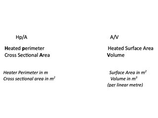
Next the section factor must be considered, as well as the fire protection period of between 30 minutes and four hours. The section factor (Hp/A) is the ratio of the fire exposed perimeter to the cross-sectional area of the steel (Table 1).
Most intumescent coating suppliers provide guidance in calculating the thickness of the coating required for a specific use and some have dedicated departments staffed with trained fire engineers who will do the calculations for you. For cellulosic fires, the products will have 3rd party certification to national or international standards (BS 5476 or EN13381). For hydrocarbon fires, the products will have certification from bodies such as Lloyd’s Register, Det Norske Veritas, or Underwriters Laboratories.
Consideration must also be given to the service environment the structure or vessel will be exposed to, as well as any special requirements such as blast resistance, high or low substrate temperature or cryogenic spill protection.
Conclusion
In addition to offering fire protection for up to four hours, intumescent coatings offer speed of application, shop or field application, aesthetic appearance and ease of inspection and maintenance.
Intumescents can protect a variety of steel surfaces from structural columns and cellular beams, to building components, vessels, and complex shapes. They can be formulated to protect against cellulosic and hydrocarbon fires including jet fires and fires resulting from explosions.
I would like to acknowledge the assistance of colleagues at JPCL, and Rick Perkins, Global Technical Manager – Fire, Sherwin-Williams Protective Marine Coatings, in compiling this article.
Brian Goldie
Table 1. Ratio of surface exposed to the fire, and “heat sink”.
Fig. 1: This graph illustrates the effect of intumescent coating on steel temperature in a hydrocarbon fire.
Fig. 2: This graph compares the heat-up rate of cellulosic and hydrocarbon fires.
Peter Elliott, Corrosion & Materials Consultancy, Inc., Las Vegas, USA.
This is the first in an occasional column, to inspire new graduates into working within our industry, by highlighting the interesting and varied aspects of a career in corrosion control, as experienced by members of the institute.
Times change, as does the understanding of corrosion and its control. As a graduating metallurgist with interests in high temperature oxidation and corrosion, my first research job, with Imperial Metal Industries, Birmingham, was the challenge of developing a metal, actually a refractory metal alloy containing tantalum, hafnium and niobium, that could survive a round trip into space. Using a high-temperature glaze from the Potteries as a coating – it worked. My interests were further enhanced by attendance at a local Institute branch meeting on corrosion by Professor T.K. (Ken) Ross, a chemical engineer, who enticed me to leave the space race and join him at what was then the University of Manchester Institute of Science and Technology (UMIST). He invited me to conduct research and asked if I knew anything about boilers. To my surprise, when I replied “no”, he replied “Perfect, I want someone with an open mind. Come and join us. When can you start?”
The return to my hometown of Manchester, to a Chemical Engineering Department, which in 1968, witnessed the creation of the Corrosion and Protection Centre – the first such academic department in the world to focus on teaching, research and industrial consulting services addressing corrosion and its control. Joining the UMIST staff my interest in boilers grew, but, by noting that metals don’t always stay hot, so did my knowledge in aqueous corrosion,including the measurement of atmospheric corrosion, which was particularly valuable – see below.
For countless years perceptions about corrosion have suggested that this often visually alarming disease is unsurmountable. Corrosion cost surveys proclaimed enormous financial losses, classed as high percentages of the Gross National (or Gross Domestic) Profit.[1] Akin to cancer and other diseases, there are parallels with corrosion control, where advances in monitoring, understanding, and treating causes with palliative cures, has grown significantly. Over the years I have noted parallels to the UK National Health Service that operates more as a National Disease Service, where exercise and healthy foods were lacking, medicines were not taken, examinations were not performed, and surgery or continued hospitalisation was required. A better understanding of corrosion, promulgated by professional societies, at least recognising (better still understanding), the interplay of thermodynamics [can a material react?] and kinetics [how fast can it be ?]. Those who seek young, experienced chemists, engineers, and metallurgists, are apparently ignorant to this oxymoron; age hardening (misquoted) reflects years of experience along with expertise.
I have continued my interest in corrosion failures – from establishing a museum in what was the UMIST Corrosion & Protection Centre so many years ago, to sharing examples at countlessmeetings and in publications.[2] I am particularly fascinated by unusual cases, for example a case that revealed a “crack” is not a crack, which brings
back memories of Turner’s Laws of Corrosion, e.g., “Nor all
that be cracked, needeth it be SCC”.[3]
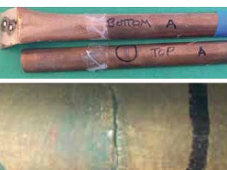
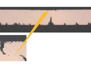
The case in question pertains to a leak in the top of a ¾”- diameter domestic cold-water pipe, which after 21 years’ service, was first attributed to a lateral crack (Figure 1A), until laboratory examination showed a complex pattern of localised pitting from the inside of the pipe (Figure 1B). The cause was apparent when the farmhouse homeowner shared the history of his convenient (for him) but unusual water sources, comprising of two years “dirty” well water, followed by 20 years of soft rainwater collected from the roof of his building. These uniquely different conditions favoured localised pitting, which progressed with sustained attack from the soft water that ultimately fully penetrated through the top of the copper pipe as the pinhole leak. The copper was not defective; there was no evidence of stress corrosion cracking.
To date, with over two million airline miles and many thousand traveled by road, my response to the question “what have you learned most?” is my knowledge of geography! In a recent litigation matter an opposing expert stated that my report was biased. A few months later – when monitored atmospheric data was available – truth prevailed. The settlement was enhanced as the bias was refuted. Telling the truth is the key to corrosion control.
References
1. Hoar report (UK), NIST, Library of Congress (USA)
2 P. Elliott, Gallery of Corrosion Damage”, Metals Handbook, 13B, ASM International, p.629-646, 2005.
3 M. E. D. Turner (Mervyn) – deceased – private communication.
This series of articles is intended to highlight industry-wide engineering experience, guidance, and focussed advice to practising technologists. It is written by ICorr Fellows who have made significant contributions to the field of corrosion management. This issue features the problem of galvanic corrosion in tanks, by Chris Googan, antiCORR (Anticorrosion Engineering Ltd).
Galvanic Corrosion – Getting the Message Across
Readers of Corrosion Management will be familiar with the perils, and mitigation, of galvanic corrosion. However, the engineering world at large is often unaware of the pitfalls. This article illustrates this with three case histories drawn from the effluent treatment industry. What is interesting is, not so much that the problems arose, but the conflicting remedial measures recommended by (so-called) corrosion experts called in
to help.
Case 1 – Poultry Processing
The first case was a waste-water treatment tank at a UK poultry processing facility. As can be seen in Figure 1, this included stainless steel processing equipment which was electrically earthed to the tank. The effluent treated was warm, intentionally aerated and, being relatively chloride-rich, was highly conducting. The tank supplier recognised this as a galvanic corrosion situation, and that it was made all the more damaging by the very high ratio of the stainless steel area to that of carbon steel at lining defects. Accordingly, the supplier warned the owners of the problem, whilst at the same time prudently withdrawing its warranty.
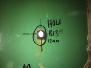
In response, the owners declined to invest in corrosion expertise. Guided by their accountant, they elected to remedy the situation by cathodic protection (CP), a plausible but, in this case, optimistic approach. Dispensing with the cost of any CP evaluation or design, some small anodes were procured. It is, however, by no means clear how, or indeed if, these anodes were actually installed. In any event, the outcome was all too predictable. Within a matter of weeks, the tank was leaking like a sieve (Figure 2), its role having changed from effluent treatment to effluent dispersal!
Fortunately, this amusing case was not particularly costly. Since the tank was relatively small, the pragmatic remedy was to rebuild it in GRP.
Case 2 – Municipal Refuse Treatment
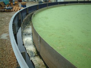
The second case involved several very large effluent aeration tanks constructed for municipal refuse treatment facilities in northwest Europe. Even before formal handover, the tanks were found to be springing leaks, to the consternation of the owners and the exasperation of the environmental authority. Investigation revealed dramatic holes in the shells (Figure 3).
The facility EPC contractor interpreted the problem as defective lining, and called in lining experts. Time and money were then invested in carrying out lining repairs in the hope that this would remedy the problem. Unfortunately, it seems the lining experts had forgotten their galvanic corrosion lessons. They missed the fact that the very well-lined carbon steel tanks contained multiple bare stainless steel nozzles. As in Case 1, the cathode to anode area ratios were enormous, so the galvanic corrosion penetration was very rapid (the steel effectively undergoing electrochemical machining). Improving the quality of the lining on the carbon steel breached a cardinal rule of managing galvanic corrosion, which is to coat the cathode. All the re-lining work achieved was that the tanks developed leaks even more quickly when returned to service.
Eventually corrosion expertise was called up. The solution was straightforward: paint the stainless steel, and install a modest sacrificial anode provision. Unfortunately, however, the EPC contractor was unwilling to engage in what it regarded as the “untried” technology of CP. Facing litigation, it took the financially punishing step of demolishing the tanks and rebuilding them in polymer-lined reinforced concrete.
Case 3 – Beverage Manufacturing Effluent
In many ways, Case 3 was similar to Case 2. It involved a number of large aeration tanks for treating effluent produced by a major European beverage manufacturer. Again, the carbon steel tanks were very well lined, but they contained stainless steel inlet piping and aeration equipment. Some credit is due to the designers who recognised the potential for galvanic corrosion. They addressed it, in accordance with good engineering practice, by ensuring that the stainless steel piping and diffusers were electrically isolated from the tank (or so they thought).
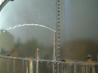
Experience tells us that a corrosion engineer can always call for electrical isolation between tanks and piping. But, in practice, the electrical engineers will always be working to achieve the opposite for the purpose of electrical safety. Thus, although the piping was electrically isolated at the point of entry to the tanks, both piping and tank walls were bonded into the common site electrical earthing system. So, notwithstanding the design intent, a galvanic cell with an adverse cathode to anode area ratio was created. Inevitably, galvanic corrosion occurred and the tanks leaked (Figure 4).
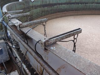
Unlike the EPC contractor in Case 2, the Owner of this facility called in corrosion, rather than lining, expertise. The corrosion specialist advised installing CP. This was accepted by the owner, and a competent contractor was engaged to supply a simple, but effective, system of sacrificial anodes suspended from cantilevered brackets fixed to the tank rim (Figure 5).
The tanks were patch-repaired and returned to service. When they were inspected five years later, the tanks were found to be in good condition. Corrosion of the tank walls, galvanic or otherwise, had been effectively suppressed.
Corrosion Community Responsibility
Doubtless, those involved in these three cases are now more aware of galvanic corrosion, and how not to manage it, than previously. Unfortunately, there remain too many engineers who, although competent in their own discipline, find themselves taking galvanic corrosion engineering decisions without even a rudimentary comprehension of the basic principles. Therefore, the question for corrosion professionals is, are we doing enough to get the right messages to the right people?
Chris Googan
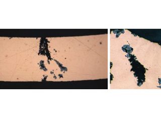
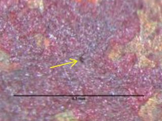
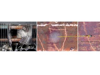
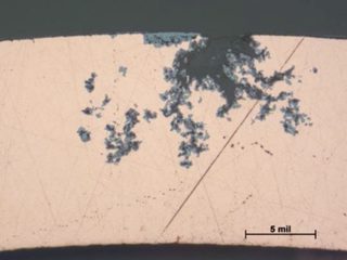
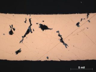
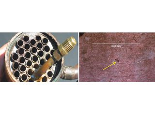
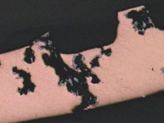
Formicary, [1] or ant-nest corrosion [2] – based upon the similarity of substrate damage with an ant’s nest (Figure 1) – dates back about fifty years. [3,4]. Formicary corrosion is a rapid acting process involving the conjoint presence of oxygen (air), moisture and a weak organic acid. It may be regarded as a “hidden” phenomenon because, (a) it is unknown to those who have not experienced it first-hand, and (b) it is challenging to identify, because the surface pin hole leak sites are often so fine that they are not visible to the unaided eye (Figure 2). Generally considered unique to copper, this insidious form of internal corrosion (Figure 1) comprises of micro-pitting networks (akin to tunnels) [5,6] that can fully penetrate small bore tubing in weeks, not years. Pin holes that occur on the outer or inner diameter surfaces are commonly surrounded by zones of discoloured copper, ranging from dull gray/black to red/brown or purple hues (Figure 2). Refrigeration-grade copper tubing, [7] used throughout the HVAC industry, was ravaged for decades (Figure 3) and 10% of all premature failures were attributed to formicary corrosion.[8]
Figure 3: Formicary corrosion common to all HVAC coil manufacturers.
Photomicrographs from different manufacturers; depth of polishing affects the visible spread of damage shown
[9] As-polished.
Copper used in other applications, including heat pumps, dehumidifiers, air coolers, heat exchangers, freezers, and chiller units, can experience formicary corrosion. Identical penetrating attack observed under coatings, lagging, sealant contact, and insulated copper piping, is typically the result of wet conditions and compounds that hydolyse to form carboxylic acids, or other chemical sources, including chlorinated organic compounds (trichlorethane, trichloethylene, etc.), and hydrolysis products from the decomposition of esters, aldehydes and alcohols (carbonyls).
Mechanism of formicary corrosion
Extensive research by the Japanese Copper Development Association [10,11] showed that formicary corrosion occurs when certain residual organic compounds degrade in the simultaneous presence of air and moisture, to produce carboxylic acids, such as formic, acetic, propionic and buteric acids. This finding was pertinent to the HVAC industry (Figure3), where synthetic lubricating oils used for forming coils, and degreasers/detergent cleaners, contained such compounds.
The general mechanism involves a micro anode, where dissolved copper ions combine with carboxylic acids (HCOOO-) to form an unstable cuprous complex Cu(CHOO), which is oxidised to form cupric formate, acetate, etc., 2Cu(CHOO)2 (cuprous complex) and cuprous oxide (Cu2O).
Microcracks with localised intergranular attack, caused by a wedging effect from the volume expansion in forming the cuprous complex and cuprous oxide [6,12] initiate at weaknesses along the corrosion pit wall, exposing more surfaces of copper to perpetuate the advancing corrosion process.
Recognising formicary corrosion
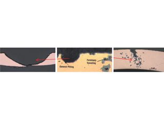
Once the locations of the fine pinholes are found – by water immersion pressure testing, macroscopy, or both – optical microscopy will confirm if the images display the unique metallography of the formicary tunnels (Figures 1, 3), which are significantly different from the smooth hemispherical contours associated with general pitting corrosion of copper (Figure 4).
General pitting by halides (chlorides, fluorides). Comparison from coil manufacturer’s report[9]. Subsurface tunnels of formicary corrosion.
Figure 4: Contrasting the two most cited common forms of coil corrosion.
As industries have become more familiar with the causes of formicary corrosion, the frequency of leaks has fallen. Research [13]1 sponsored by the Air Refrigeration Technology Institute (ARTI), to develop a reproducible screening method to determine the mechanisms and effects of corrosion,[14] resulted in a hydrolytic stability test, which uses ion chromatography to ensure that lubricant drawing oils and finning lubricants are free of carboxlic species. A separate pre-screening hexane rinse of copper tubing, provides evidence of residues with carboxylic species identified using Fourier Transform Infrared Spectroscopy (FTIR). Several HVAC equipment manufacturers have made material and design changes, including, tin-plated copper hair pins and tubing less prone to attack, ductless AC units with moisture filters, and all-aluminium tubing and fin construction.
Currently, indoor coil leak failures by formicary corrosion have been attributed to energy- efficient buildings with decreased ventilation that promulgate higher concentration levels of carboxylic acids from building materials, woods, adhesives, disinfectants, cleaning solvents, vinegar seasonings, liquid smoke, cosmetics, etc.
Selected examples of formicary corrosion leakages presented herein, include, HVAC coils with pin holes on the outer (OD) or inner (ID) diameter surfaces (Figures 5, 6), and a heat exchanger from a fabrication shop (Figure 7).
OD-initiated formicary intrusions in defect-free copper.
ID of split tube with purple/red-brown surface film. pin hole in purple/red-brown surface film.
ID-initiated formicary intrusions in defect-free copper.
Open end of heat exchanger. Pin hole in purple/red-brown surface film on ID of tube.
ID-initiated coarse formicary tunnel in defect-free copper.
Pin holes in copper are not always formicary corrosion
Some examples of formicary corrosion have been presented in the previous paragraphs, with brief comments about how it can be assessed and generally avoided by using screening tests on the copper tubing and of the contact environment. Presented In the following paragraphs are some examples where pin holes were wrongly ascribed to formicary corrosion.
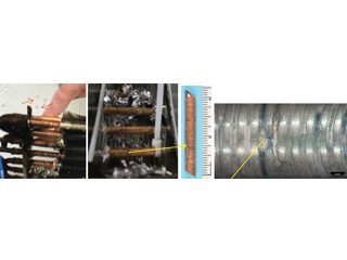
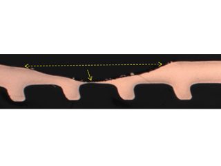
• Failed HVAC installation – pin holes found following about 2 to 3 years service were claimed by the coil supplier[15] to display the “worst case of formicary corrosion ever seen”. They were incorrect. The observed damage (Figure 8), and the optical photomicrographs (Figure 9), show no micro-pitting networks – the chacteristic feature for formicary corrosion.
The leak locations along the copper tubing appear to be associated with the design and assembly of the ceiling-mounted units. The repeating geometric pattern of hemispherical- shaped wastage zones close to, or in direct contact with, the aluminium fins, (Figure 9) suggests a modified form of Rosette corrosion,[16] combined with crevice corrosion,[17] and galvanic attack. [18] The additional pitting in the vicinity of the through-wall leaks (Figure 8) is indicative of some form of synergy between these processes.
Rosette corrosion is a somewhat recently recognised corrosion phenomenon,[19] which was encountered in copper hot water cylinders fitted with aluminium anodes. The anodes were installed to prevent type 1 pitting corrosion and was very successfully applied for over 30 years.[20] However, corrosion failures were occurring at the bottom of these cylinders where the water was cooler. This phenomenon was attributed to the interaction of the copper-aluminium galvanic couple [21] and certain impurities in the water that generated reducing species that led to the corrosion at the bottom of the cylinders. This form of corrosion has been essentially eradicated in the United Kingdom, when specifications disallowed the use of aluminium protector rods in 2002.[22] The removal of the aluminium anode and a redesign of the hot water cylinders eliminated the cold bottom thus promoting the growth of a semi-protective corrosion layer.
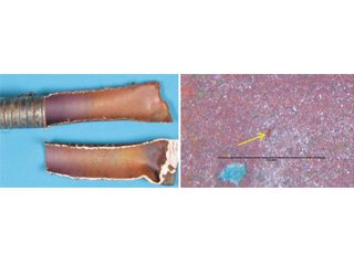
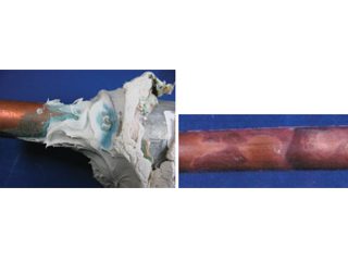
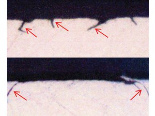
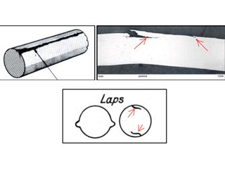
• Formicary corrosion by contact with sealant – accounting for a blue discoloration surrounding a usually white-colored acoustic sealant (Figure 10), a recent publication wrongly implied that tube failure by formicary corrosion and environmentally assisted cracking (EAC) from such contact was probable. [23] Long-term simulation testing with high relative humidities and temperatures showed this was most unlikely.[24] Without a sustained presence of air and moisture, through-wall penetration by formicary corrosion – a rapid process, as noted earlier – is not expected. Mechanical laps from tube-forming (Figure 10) were wrongly interpreted as EAC with formicary corrosion. This matter was addressed nine years ago, [25] the blue discoloration was nothing more than an aesthetic issue.
Discussion and conclusions
Formicary corrosion is regarded as a subsurface network of microscopic-corroded tunnels that are considerably larger than the tiny pin holes they connect to, [27] which presents a challenge to those who are aware of the “usual” localised phenomenon of pitting corrosion,which ranked fourth from seven common sources of copper tube corrosion based on over 1,500 investigations over 25 years in domestic water systems. [28] This source noted that all can be mitigated cost-effectively provided that, water quality is maintained, copper tube systems are properly designed and installed, and systems are operated within design parameters.
Formicary corrosion may be active if:
• fluids leak in weeks or months.
• surface zones of discoloured copper (dull gray/black to red/brown or purple hues) are evident.
• copper exposed to air (oxygen), moisture and a weak organic acid, e.g., carboxylic acids, (formic, acetic, propionic, buteric).
• copper exposed to other chemical sources, including chlorinated organic compounds and hydrolysis products from decomposition of esters, aldehydes and alcohols (carbonyls).
• wet conditions persist under coatings, lagging, sealant contact, and insulated piping with compouds that hydrolyse to form carboxylic
acids.
Success in dealing with formicary corrosion, like many other forms of corrosion, is dependent on knowing what it is; knowing how to recognise it; knowing what causes it; and focusing on control, rather than elimination – the realistic goal. [30]
Acknowledgements
The author kindly acknowledges the contributions of Mr. Fred Sherman, Sr. Materials Analyst, for his meticulous contributions to the metallography and laboratory testing, and Mr. Brad Krantz, VP of Laboratory Services, for support and access to Corrosion Testing Laboratories, Newark DE.
References
1.
“For-mi-car-y”: from Medieval Latin, Formica ‘ant’, defined as a nest of ants or an anthill, Oxford Dictionary.
2.
S. Yamauchi, K. Nagata, S. Sato, M. Shimono, J. Japanese Copper & Brass Research Assocn., 22, p.132, (1981).
3.
J.O. Edwards, R.J. Hamilton, J.B. Gilmore, Materials Performance, NACE International, 16, 9, p.18, (1977).
4.
J. M. Keyes, International Copper Research Association Symposium, Belgium, June (1965).
5.
P. Elliott, R.A. Corbett, “Ant Nest Corrosion – Exploring the Labyrinth”, Corrosion Reviews, 19, No. 1, p.1-14, (2001).
6.
R.A. Corbett, P. Elliott, “Digging the Tunnels”, Corrosion Reviews, 20, No. 2, p.51-66, (2002).
7.
DHP copper, alloy C122, UNS C12200, 99.90% copper, ASTM B280.
8.
Go Isobe et al, NACE Corrosion Asia, Paper 105, Singapore, September (1992).
9.
Carrier Corporation, Industry Research Reports “Indoor Coil Corrosion” (2007 to 2011).
10.
T. Notoya, T. Hamamoto, K. Kawano, Corrosion Engineering (Japan), 367, 2, p.1, (1988).
11.
T. Notoya, “Localized “Ant Nest” Corrosion of Copper Tubing and Preventive Measures”,Materials Performance, NACE International, 32, 5, p.53, (1993).
12
D. M. Bastidas, I. Caynela, J.M. Bastidas, CENIM – National Centre for Metallurgical Research, CSIC, Avda, Madrid, Spain, “Ant-nest corrosion of copper tubing in air-conditioning units”, Revista de Metalurgia, 42 (5) September/October, p.367-381, (2006).
13.
Air Refrigeration Technology Institute (ARTI), Report, 21-CR Research Project 611-50055, R. A. Corbett, Corrosion Testing Laboratory, Newark, DE, with input from P. Elliott and T. Notoya, (2003).
14.
R.A. Corbett, “The Development of a Reproducible Screening Method to Determine the Mechanisms and Effects of Organic Acids and other Contaminants on Corrosion of Aluminium-finned copper tube Heat Exchanger Coils, Corrosion 2004, Paper 04321, NACE International,
New Orleans, LA, (2004).
15. Private communication.
16.
Rosette corrosion – the premature failure of copper hot-water cylinders fitted with aluminium rods to prevent Type 1 copper pitting: R.J. Oliphant, Journal of Chartered Institute of Water & Environmental Management, UK, vol 14, p. 207, July (2007). R.J. Oliphant, Causes of Copper Corrosion in Plumbing Systems, Foundation for Water Research Review, FR/R0007, May (2003).
17.
Crevice corrosion – localised corrosion of a metal or alloy surface at, or immediately adjacent to, an area shielded from full exposure to the environment because of close proximity of the metal or alloy to the surface of another material or an adjacent surface of the same metal or alloy. NACE/ASTM G193-12d, Standard Terminology & Acronyms Relating to Corrosion, (2010).
18.
Galvanic corrosion – accelerated metal corrosion because of electrical contact with a more noble metal or nonmetallic conductor in a corrosive environment. NACE/ASTM G193-12d, Standard Terminology & Acronyms Relating to Corrosion, (2010).
19.
R. Francis, Corrosion of Copper and its Alloys: A Practical Guide for Engineers, NACE International, (2010).
20.
R.J. Oliphant, Journal of Chartered Institute of Water & Environmental Management, UK, vol 14,p. 207, July (2007).
21. V.F. Lacey, British Corrosion Jnl., 7, p.36, (1972).
22.
P. Munn, Causes of Copper Corrosion in Plumbing Systems,3rdEdition, Report FR/R0007, Foundation for Water Research September, (2017).
23.
K. Steiner, “Formicary Corrosion and EAC of Copper Tubes in Contact with Building Sealant”, AMPP Annual Conference, Paper No.17846, AMPP, San Antonio, TX, (2022).27.
24.
P. Elliott, “Blue-Stained Sealants Do Not Imply Catastrophic Corrosion of Medical-Grade Copper Piping”, Materials Performance, NACE International, 52, 6, p.57, (2013).
25. ibid.
26.
Laps sourced from: ASM International, Volume No. 11, Failure Analysis & Prevention, Failures Related to Metalworking, p.82, (2002); Rollason E.C., Metallurgy for Engineers, 4th Ed., Edward Arnold, p. 62, (1973).
27. A.H. Brothers, Mainstream Engineering, Rockledge, Fl – internet search.
28.
J. R. Myers and A. Cohen, “Copper-Tube Corrosion in Domestic-Water Systems”, HPA Engineering: Supplement, June, (2005).
29.
P. Elliott, “Fight Formicary Corrosion”, Chemical Processing, p. 37, November (2005).
Peter Elliott
Full section perforation via formicary “tunnels”. 150X Unique “ant”. 500X
Figure 1: Through-wall formicary corrosion and detail of local “ant”.
Removing aluminium fins to expose tiny holes. Soapy bubbles locate miniscule holes by immersion testing with nitrogen.
Figure 5: OD attack in HVAC coil promoted by cleaning/disinfecting wipes containing ethanol, propanol, and a propionate (a carboxylic specie).
OD-initiated formicary intrusions in defect-free copper.
ID of split tube with purple/red-brown surface film. pin hole in purple/red-brown surface film.
Figure 6: ID attack in HVAC tubing by detergent or degreaser contaminated with carboxylic specie. The tube was drawn using lube oil free from carboxylic acids.
ID-initiated formicary intrusions in defect-free copper.
Open end of heat exchanger. Pin hole in purple/red-brown surface film on ID of tube.
Figure 7: ID attack in enhanced copper tubing in a heat exchanger bundle from a fabrication shop. Surface products contained carboxylic (formate) species.
ID-initiated coarse formicary tunnel in defect-free copper.
From left to right. Bubbles show leaks. Aluminium fins stripped to access copper sample. Macro of pinholes on the OD surface.
Close up of OD pinhole leak and surrounding small pits.
Figure 8: Pin hole and other localised pits in one of many HVAC indoor coils.
Detail of OD leak location. As polished. 80X
Figure 9: Through-wall leak location coincides with a repeating geometric pattern of smooth hemispherical pits aligned with the aluminium fin locations.
Blue-stained white sealant; 18 months in service. Superficial etch stains on copper with sealant removed.
Shallow surface laps under sealant. As polished. 500x. Shallow surface laps remote from sealant. 500x
OD – longitudinal surface lap.Photomicrograph of surface laps.Schematics of OD and ID laps.
Figure 10, Blue-stained sealant on copper tubing in hospital installation and shallow surface laps [26] misinterpreted as EACs and the initiation of formicary corrosion.
This series of articles is intended to highlight industry-wide engineering experiences, guidance, and focused advice to practising technologists. The series is written by ICorr Fellows who have made significant contributions to the field of corrosion management. This issue features articles on the use of existing pipelines for the transport of hydrogen, by Frank Cheng, Dept. of Mechanical & Manufacturing Engineering, University of Calgary, Canada, and on an interesting aspect of copper corrosion, by Peter Elliott, Corrosion & Materials Consultancy, Inc., Las Vegas, USA.
Suitability of existing pipelines for hydrogen service
It is believed that hydrogen will play a critical role in energy transition, and achievement of the 2050 net-zero emission goal. Hydrogen delivery is integral to the entire value chain of hydrogen economy. Compared with other transportation modes, such as tankers, pipelines provide an economic and efficient means to transport gaseous hydrogen with a high transportation capacity over long distances [1]. Particularly, repurposing existing natural gas pipelines is “a low-cost option for delivering large volumes of hydrogen” [2], contributing to accelerated realisation of a full-scale hydrogen economy, while saving high initial capital costs of constructing new hydrogen-dedicated pipelines.
However, hydrogen embrittlement (HE) can occur on pipelines transporting hydrogen in either blended or pure form, compromising the structural integrity to cause pipeline failures. Compared with newly constructed pipelines, the existing pipelines, after a long time of service in the field, include additional challenges to address in terms of the HE occurrence when converted for hydrogen service.
What is hydrogen embrittlement?
Hydrogen embrittlement is a general term describing the degradation of a material’s (mainly metal) properties and structural integrity, due to hydrogen-metal interactions. HE is a concept serving as an ‘umbrella’ under which many different modes of metallic degradation induced by hydrogen are referred to.
The first mode of HE phenomenon is hydrogen-induced cracking (HIC), which is also regarded as the most dangerous mode of HE-associated materials failure. The HIC occurs when the hydrogen atom concentration at a local site exceeds a threshold value under a given stress condition. Generally, the threshold H atom concentration required to initiate cracks in steels decreases with an increased stress. Many mechanisms or theories have been proposed to explain the HIC occurrence, such as hydrogen-enhanced localised plasticity (HELP), hydrogen-enhanced decohesion (HEDE), adsorption- induced dislocation emission (AIDE), and hydrogen-assisted microvoid coalescence (HAMC) [3].
Presently the dominant mechanisms for HIC of steels are the HEDE and HELP [4]. According to the HEDE mechanism, H atoms can weaken bonds between iron atoms in steels and when the external stress exceeds the atomic cohesive strength of Fe in the presence of H atoms, microcracks can be initiated. The HELP mechanism proposes that H atoms accumulate at dislocations to decrease the interfacial elastic energy between mobile dislocations, enhancing the mobility of the dislocations. As a result, the local deformation can occur at a lowered stress, facilitating plastic deformation and cracking occurrence. The HIC can initiate whether on the surface of a metal (i.e., external HIC,) or inside the metal (i.e., internal HIC).
The second mode of HE is hydrogen blistering, where the H atoms entering the metal become recombined to form hydrogen molecules (H2) at the trapping sites, such as voids. The elevated pressure due to accumulation of H2 molecules at a local site can cause formation of a blister (or bubble) on the metal surface. This hydrogen blistering usually occurs on low-strength and ductile metals where the bubbling process does not initiate cracks. Instead, the metals’ experience a remarkable local plastic deformation. If the metals have a high strength and limited ductility, the hydrogen-elevated pressure can cause cracking by the so-called hydrogen internal pressure (HIP) mechanism.
The most common mode of HE phenomenon is degradation of mechanical properties of the affected metals, which is usually shown as a reduction in fracture toughness and ductility. The direct evidence of this mode is the decrease in fracture elongation in the stress-strain curve measured on hydrogen- charged metals, compared with the tensile behaviour of hydrogen-free metals. Generally, a limited amount of hydrogen atoms may not be sufficient to initiate cracks, but can cause a reduction in ductility of the metals.
Uniqueness of pipeline hydrogen embrittlement in high-pressure gaseous environments
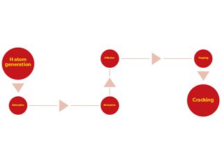
HE can occur on pipelines in high-pressure gaseous hydrogen environments. The entire HIC processes include six steps, i.e., generation of H atoms, adsorption of the H atoms on the steel surface, absorption of the H atoms by permeating into the steel, diffusion of H atoms in the crystalline lattice, trapping (accumulation) of H atoms at local sites, and the crack initiation, as schematically shown in Figure 1. The first three steps, i.e., H atom generation, adsorption, and absorption, depend heavily on the environment, whereas the other steps of diffusion, trapping and cracking, mainly rely on the metallurgical factors.
Figure 1. Entire processes for HIC occurrence on metals (steels).
Previous work demonstrated that H atoms can generate and become adsorbed on steel surfaces through a so-called dissociative adsorption mechanism in high-pressure gaseous environments [5]. The Gibbs free energy changes for production of H atoms from gaseous H2 molecules are negative, indicating a thermodynamic feasibility, under pipeline operating conditions with typical temperatures, pressures and H2 gas/natural gas blending ratios. Moreover, the generated H atoms can adsorb stably at On-Top (OT) and 2-fold (2F) Cross-Bridge sites of the Fe (100) crystalline plane, while the hydrogen adsorption at 2F sites is more stable due to a higher electron density and a stronger electronic hybridisation between Fe and H. Upon entering the steels, the H atoms predominantly stay at tetrahedral void sites due to a low energy path and exothermic feature. It has been noted that a uniform distribution of H atoms at the tetrahedral voids in a crystalline lattice would not cause HE or HIC, if the amount of H atoms is within the limit of H solubility. However, the local solubility can be exceeded if H atoms diffuse towards high stress zones, or become trapped at metallurgical features such as grain boundaries, dislocations, and non-metallic inclusions.
Nowadays, substantial studies have been conducted to investigate HE of metals, including pipeline steels, in aqueous environments, where most investigations focused on H atom generation during steel corrosion or cathodic over-protection. Four major differences exist in H atom generation and permeation in steel between a gaseous environment (“gaseous” hydrogen) and the aqueous environment (“cathodic” hydrogen), as listed in Table 1, making it infeasible to directly use data obtained in aqueous environments for HE investigations on pipelines in high-pressure gaseous environments. First, the amount of “cathodic” hydrogen generating during electrochemical cathodic charging, either potentiostatically or galvanostatically, is always substantial. A significant H atom concentration gradient exists between the outside and inside subsurface of the steel. However, the amount of H atoms generated in a gaseous environment is usually limited. After several months of exposure of a pipe steel to high-pressure (10 MPa) H2 gas, the measured H concentration is less than 1 ppm [6]. Secondly, due to the high concentration gradient of H atoms across the steel surface, the permeation of “cathodic” hydrogen is always one way, entering the steel from the adsorption to absorption state. As a comparison, the “gaseous” H atoms, even entering the steel and becoming absorbed inside, can still leave the absorption site and change to adsorption state [5]. Thus, the permeation of “gaseous” hydrogen is reversible. Third, the electrochemical hydrogen-charging usually generates reproducible results, making the testing method (i.e., the Devanathan-Stachurski cell) a standard method for hydrogen atom permeation tests [7]. Although there has been limited work to measure the H atom permeation in gaseous environments, the obtained data are usually scattered, and sometimes, even conflict each other. Finally, both constant concentration model and constant flux model have been developed to fit the electrochemical cathodic H-charging results to derive the H permeation parameters such as H diffusivity, subsurface H concentration and trapping density [8]. To date, a model applied for “gaseous” hydrogen permeation has not been established. Due to the differences listed, the testing results and modeling methods for aqueous “cathodic” hydrogen testing cannot be used for gaseous hydrogen permeation testing.
‘Gaseous’
hydrogen ‘Cathodic’
hydrogen
Amount generated to adsorb on steel surface Limited Substantial
Permeation pathway Reversible between adsorption and absorption One way from adsorption to absorption
Testing results Scattering, and sometimes, controversial Reproducible
Numerical model to derive hydrogen permeating parameters None Constant concentration model and constant flux model
Table 1. Comparison of the H atom generation and permeation in steels in a gaseous environment and in an aqueous environment.
Additional challenges when repurposing existing pipelines for hydrogen service
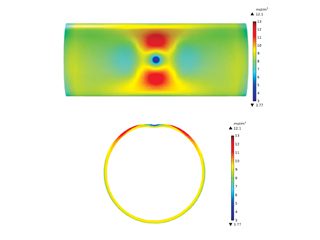
After a long time of service in the field, existing pipelines become aged and contain various surface defects such as dents, corrosion, scratches, winkles and microcracks. These defects, if passing the assessment criteria [9], would not be required to be repaired, and the pipelines can continue to operate. However, they serve as effective traps to accumulate H atoms. Particularly, dents, a common type of mechanical damage present on pipelines, is a permanent inward deformation on the pipe body, greatly changing the local stress and strain distributions. As a result, the H atoms, once entering the pipe steels, tend to diffuse towards the dent and accumulating locally. Modeling results showed that there were maximum H atom concentrations at both sides of the dent along the circumferential direction, as shown in Figure 2. The H atom distribution coincided with the distribution of hydrostatic stress on the pipe. Moreover, as the dent depth increases, the H atom concentration increases at the local area.
Figure 2. Distributions of the H atom concentration (unit: mol/m3) on an X52 steel pipe segment containing a constrained dent and the cross-sectional view. The dent depth is 3% of pipe outer diameter and the internal pressure is 10 MPa [10].
Different from a dent, a corrosion defect causes metal loss on the pipe wall. Moreover, the corrosion defect is dynamic in nature, and will grow with time in the service environment. It is acknowledged that corrosion is one of the primary mechanisms causing pipeline failures. Generally, the presence of a corrosion defect on the pipe body can decrease the pressure-bearing capability of the pipelines.
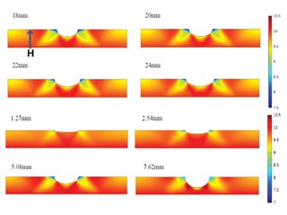
Thus, many standards and codes have been developed for corrosion defect assessment. Similar to a dent, if a corrosion defect passes the assessment criteria, the corroded pipelines can continue to operate, without a need to repair the corrosion defect, but a cautious monitoring of the defect growth should be followed. It was confirmed that the H atoms which were originally distributed in the crystalline lattice of a steel would diffuse towards the corrosion defect. Moreover, as the corrosion defect length reduces and the depth increases, the H atom concentration becomes more apparent, as seen in Figure 3.
Figure 3. Distributions of the H atom concentration (unit: mol/m3) on an X52 steel pipe segment containing a corrosion defect with varied lengths and depths [10].
A technical assessment programme for the suitability of aged pipelines in hydrogen service
Obviously, a technical programme must be developed to assess the suitability of the existing aged pipelines to transport hydrogen in either pure or blended form. The assessment should consider the synergism of steel metallurgy, stress, and hydrogen, on HE or HIC occurrence. Particularly, the surface defects present on the pipelines should be paid much attention, in addition to the metallurgical features such as grain boundaries, dislocations and non-metallic inclusions, which are effective hydrogen traps. The specific service history of the pipelines which were made of various grades of steel should be considered, and the technical assessment should be conducted case by case. Once successfully developed, the technical assessment programme will be able to: evaluate the possibility of H atoms generation and the amount of H atoms adsorbed on the steel surface under pipeline operating conditions, quantify the accumulated H atom concentration at the surface defects and metallurgical features under given conditions, estimate the threshold H atom concentration at a local defect to initiate cracks under a certain stressing condition, rank the HE susceptibility of the aged pipelines while considering the metallurgical and stress factors, and recommend proper operating conditions (e.g., temperature, pressure and blending ratio) to minimise and eliminate pipeline HE in high-pressure gaseous environments.
References
[1]
A.S. Hawkins, Technological Characterization of Hydrogen Storage and Distribution Technologies, UKSHEC Social Science Working paper no. 21, Policy Studies Institute, London, UK, 2006.
[2]
U.S. Department of Energy, Hydrogen Pipelines, Washington DC, US, 2020.
[3]
Yinghao Sun, Y. Frank Cheng, Hydrogen-induced degradation of high-strength steel pipeline welds: A critical review, Eng. Fail. Anal, 133 (2022) 105985.
[4]
M.B. Djukic, G.M. Bakic, V. Sijacki Zeravcic, A. Sedmak, B. Rajicic, The synergistic action and interplay of hydrogen embrittlement mechanisms in steels and iron: Localized plasticity and decohesion, Eng. Frac. Mech., 216 (2019) 106528–106561.
[5]
Yinghao Sun, Y. Frank Cheng, Thermodynamics of spontaneous dissociation and dissociative adsorption of hydrogen molecules and hydrogen atom adsorption and absorption on steel under pipelining conditions, Int. J. Hydrogen Energy, 46 (2021) 34469-34486.
[6]
G. Golisch, G. Genchev, E. Wanzenberg, J. Mentz, H. Brauer, E. Muth
mann, D. Ratke, Application of line pipe and hot induction bends in hydrogen gas, J. Pipeline Sci. Eng., 2 (2022) 100067.
[7]
M.A.V. Devanathan, Z. Stachurski, The adsorption and diffusion of electrolytic hydrogen in palladium, Proc. Royal Soc., A270 (1962) 90-102.
[8]
Y.F. Cheng, Analysis of electrochemical hydrogen permeation through X-65 pipeline steel and its implications on pipeline stress corrosion cracking, Int. J. Hydrogen Energy, 32 (2007) 1269–1276.
[9]
Guojin Qin, Y. Frank Cheng, A review on defect assessment of pipelines: Principles, numerical solutions, and applications, Int. J. Press. Vessel Pip., 191 (2021) 104329.
[10]
Frank Cheng, Hydrogen transport in aged pipelines II. Technical assessment of the susceptibility to hydrogen embrittlement, AMPP / ASM International Calgary Chapter Luncheon, Calgary, Canada, Oct. 19, 2022.
This article will look at the Electrochemical Noise Method for corrosion monitoring. Firstly, what are its attractions?
Well, it’s as unintrusive as its possible to get, just using the fluctuations which are produced naturally by the corrosion process to tell us the corrosion rate and also, by looking at the plots, the corrosion processes (the degree to which it affects the item being measured is maybe as little like the effect on the star of using the James Webb telescope to obtain its distance based on the red shift!). Secondly the measurement is quick (a few minutes) and interpretation of results is intrinsically simple. It can operate on battery power and the equipment is portable and with appropriate sensing electrodes it can be used for continuous monitoring. The remainder of this article gives examples of how results can be obtained using the ENM technique, not just from organic coatings, but also from reinforcing bars in concrete, and to screen inhibitors. The inhibitors work is part of an ongoing programme at Nottingham university and the other two pieces of work were done by students in Northampton.
First how does the electrochemical noise arise, and what do the results look like?
Rn= v/ I 1
Where Rn is noise resistance,
v and I are the standard deviations of voltage and current values, respectively, measured during a given time period is given by:
V2 = Vj−Vm)2/(n−1) 2
I 2= Ij−Im)2/(n−1) 3
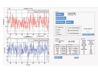
In equations 2 and 3, Vj is the voltage value measured at the jth time interval, Vm is the mean voltage in the given period of time, Ij is the current value measured at the jth time interval, Im is the mean current in the given period of time, and n is the number of time intervals. [1] For coatings, Rn equates to the DC resistance (Rdc), and EIS (0.1 Hz impedance). [2] There is evidence from this work and others that when there is significant corrosion rate, Rn relates to the value Rp obtained from Linear Polarisation Resistance (LPR). The analysis software creates a value of Rn, and typical ENM data are shown in Figure 1.
The first application of the ENM method described is to an anti-corrosive organic coating system.
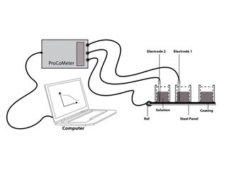
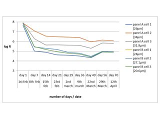
The actual Noise arrangement used is known as the single substrate (SS) method, diagrammatically shown in Figure 2. You need two working electrodes for noise measurements, and with the single substrate arrangement you can have these as two areas of painted substrate on the same panel, isolated in lab work, by being contained in cells (but in site work, a dry piece of coated steel with a Calomel electrode in each cell, is adequate). The third electrode (reference) is the panel itself. When you examine an organically coated metal, the noise signal tends to be attenuated by the ionic resistance of the coating, and you end up with that resistance being dominant. In this example, the coating was applied to Q panels, cells were attached, and the coated area within each cell was exposed to 0.1 M chloride solution for several months (with occasional topping up). The ENM results were compared against DC resistance. The results are shown in the Figure 3. As can be seen, some areas of coating started with low values of resistance which tended to drop with time, while others had higher initial values, and these remained high. There was a strong correlation between the Rn values, the Rdc values, and the visual appearance. Also, the effects of thickness and number of coats were investigated. Thickness proved more critical than number of coats, although both were important, the higher the thickness the more protective the coating. The advantage of the electrochemical measurement over visual observation is, a) it tells you what is happening earlier, b) It indicates problems when you cannot see what is going on, c) it can be automated, and d) it gives you a number!
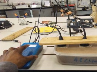
These advantages also apply in the case of the second example, that is measuring the corrosion rate of reinforcing bars in concrete. This is little more complicated to set up. The lab work was designed to be a precursor to taking the equipment out to site so non-glass electrodes were used viz solid-state silver /silver chloride solid electrodes, which worked just as well as Calomel electrodes. There is an ENM arrangement which can be applied to a coating or to concrete, which is the NOCS (No connection to the substrate) arrangement. This offers the attraction of being able to get a result without actually making any connection to the rebar itself. The experimental set up is shown in figure 4 and some typical results in Table 1. This work involved two sets of three bars in mortar, one of which contained no added chloride, and the other of which had 4% added chloride. The results were quite clear, the bars in the 4% were corroding (corrosion rate inversely proportional to Rn) many times faster than the bars in the 0% NaCl, although there was some minor variation between bars. Unlike the coating work, we cannot check these particular samples yet as they are still under test and have not been broken open. However previous published work [3] showed beyond reasonable doubt that the Rn value correlated very well to the subsequently observed corrosion.
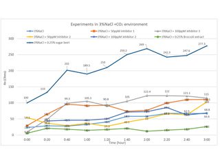
The third example is testing inhibitors This was driven by the wish to test green inhibitors and see if they could be used as alternatives to conventional more toxic inhibitors such as propargyl alcohol. The application considered was the need to inhibit corrosion of the steel pipes used to carry the CO2 saturated oil, containing some sea water. The experimental set up is shown in Figure 5. Two small nominally identical rectangular steel samples were contained in a sample holder made employing the ‘additive manufacturing’ process (a form of 3D printing). In this case it was from an ABS polymer powder. The black blanking-off compound was provided by an anticorrosion coating manufacturer. It was found essential to stir the solution to get reproducible results, although in practise a significant flow rate is likely. Some results are shown in Figure 6, where a particular green inhibitor (sugar beet) proved more effective than conventional inhibitors. The lab investigation compared the ENM method both against corrosion loss by ICP-MS analysis, and also against the more commonly used LPR method. This work has not yet appeared in a journal publication. But a paper has been submitted to EUROCORR 2022.
This has been whistle stop tour showing the application of this ENM technique to three different fields. If anybody wants to find out more, get in touch with the author.
1) Yang, L. and Chiang, K.T. (2010) On-line and real-time corrosion monitoring techniques of metals and alloys in nuclear power plants and laboratories. Understanding and Mitigating Ageing in Nuclear Power Plants., pp. 417-455
2) Comparison of ENM, EIS and DC Resistance for Assessing and Monitoring Anti-Corrosive Coatings Douglas J Mills JCSE 2000
3) Mills, D.; Lambert, P.; Yang, S. Electrochemical Noise Measurement to Assess Corrosion of Steel Reinforcement in Concrete. Materials 2021, 14, 5392. https:// doi.org/10.3390/ma14185392
Acknowledgements
The author would like to acknowledge the assistance of Paul Lambert relation to the concrete project, and extend his thanks to students: Tian Yang Lan, Reuben Osahon and Chiata Collins for permission to publish some of their results. And to DCVG company for providing The Noise Measuring Equipment.
Douglas J Mills
Figure 1: Typically Noise plots of current and voltage against time.
Figure 2: Schematic diagram showing how ENM is applied to coated metal (Single Substrate arrangement) (Solution is typically 0.1 M NaCl).
Figure 3: Typical results obtained from Hammerite coating of Resistance against time.
Figure 4: Set up for measuring Rebar in concrete using NOCS arrangement of ENM.
We use cookies to optimize our website and our service.
Functional
Always active
The technical storage or access is strictly necessary for the legitimate purpose of enabling the use of a specific service explicitly requested by the subscriber or user, or for the sole purpose of carrying out the transmission of a communication over an electronic communications network.
Preferences
The technical storage or access is necessary for the legitimate purpose of storing preferences that are not requested by the subscriber or user.
Statistics
The technical storage or access that is used exclusively for statistical purposes.The technical storage or access that is used exclusively for anonymous statistical purposes. Without a subpoena, voluntary compliance on the part of your Internet Service Provider, or additional records from a third party, information stored or retrieved for this purpose alone cannot usually be used to identify you.
Marketing
The technical storage or access is required to create user profiles to send advertising, or to track the user on a website or across several websites for similar marketing purposes.