
Hani Almufti, Technical Lead, Cogbill Construction (RedLineIPS), USA.
Meet the Author
Hani Almufti is Engineer and Manager of Strategic Development at Cogbill Construction (RedLineIPS), where he leads product strategy, materials selection, and technical guidance for metallic and non-metallic pipe support systems. He holds a B.S. in Industrial Engineering and is a Master’s candidate in the same field. With 15+ years in pipe supports—including a decade focused on offshore energy corrosion—he specialises in corrosion under pipe supports (CUPS) and the performance of FRP/composite and metallic supports. His expertise spans corrosion mitigation, reliability engineering, and process improvement, with a sustained focus on reducing risk, noise/vibration, and lifecycle cost across onshore and offshore assets.

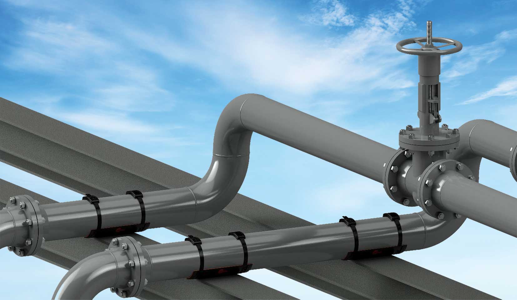
Photo 1: Installed System On Pipe Gantry.
1. Introduction
Pipe-support interfaces are convergence points for several degradation modes in industrial and offshore piping: corrosion under pipe supports (CUPS), vibration, structure-borne noise, and fatigue. On offshore platforms and FPSOs, major operators have reported that these risks are heightened by salt-laden atmospheres, hull motion, and restricted access, while the pipe–pad contact remains difficult to inspect [1].
Conventional mitigations—welded metallic pads, thermoplastic half-rounds, and epoxy-bonded plates—can re-establish galvanic paths, trap electrolyte, or require hot work and cure time. Maintaining seal integrity, alignment, and controlled slip becomes increasingly challenging as coatings wear and thermal cycles accumulate [1]. The RedLineIPS SmartPad System is a fully non-metallic support interface comprising a load-spreading FRP saddle, a bonded closed-cell elastomeric gasket (Hydroseal), and FRP bands/buckles.
Together, they electrically isolate the pipe from the steel support, seal the pipe–pad contact to discourage moisture films, provide viscoelastic damping at the interface, and relocate thermal slip to a controlled, low-friction plane on the saddle/support side. This paper outlines the design rationale, installation approach, and third-party proofs, and summarises field experience from a Gulf Coast of Mexico chemical plant retrofit programme.
2. The SmartPad System
2.1 Composite FRP SmartPad (Saddle Wear Pad)
2.1.1 Construction and geometry
Structural fibre-reinforced polymer (FRP) saddle fabricated from continuous-strand mat (CSM) in a vinyl-ester matrix, moulded to standard pipe curvatures of 1/2” to 72” NPS. The crown radius and contact width are sized to spread load over a broad arc, keep local bearing pressure low, and maintain stable seating under thermal and dynamic loads.
2.1.2 Functions at the pipe–pad interface
• Load distribution: Spreads the pipe’s weight over a wider area so no small spot takes all the pressure—reducing dents and coating damage.
• Electrical isolation: Non-conductive composite interrupts metal-to-metal continuity (limits galvanic coupling to support steel).
• Coating protection: Smooth, inert bearing surface reduces abrasion during thermal slip and vibration.
• Offshore durability: Vinyl-ester chemistry with UV inhibitors tolerates chloride-rich, marine atmospheres.
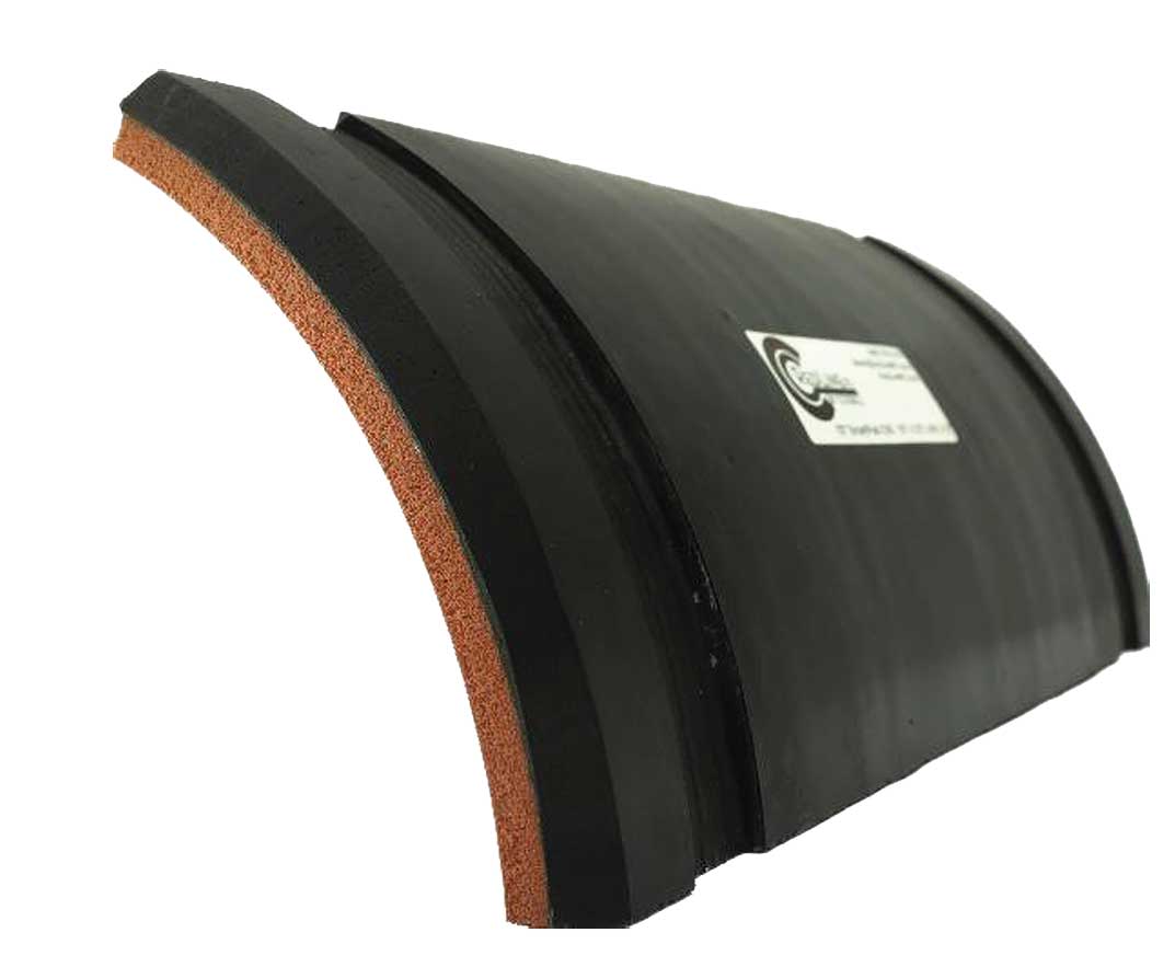
Photo 2: SmartPad Exoskeleton with Grooves for Bands.
2.1.3 Typical Material Properties
• Resin system: Vinyl ester; reinforcement: CSM; glass content: ~35–40 wt%.
• Compressive strength (ASTM D695): ~25,000 psi
(172 MPa) [2].
• Flexural strength (ASTM D790): >30,000 psi (207 MPa).
• Continuous service temperature: -60°F to 400°F (-51°C to 204°C).
• UV resistance: High (integral inhibitors).
• Fire behaviour: Fire-retardant formulation (rating available on request).
2.1.4 Manufacture and Integration
Hand lay-up with controlled cure to achieve low void content and uniform fibre wet-out. Finished edge radii and surface roughness are controlled to minimize coating gouge. Saddle curvature and contact-width tolerances support repeatable fit and clamp preload. The FRP saddle provides the load-bearing, isolating substrate for the bonded closed-cell gasket and FRP banding within a fully non-metallic load path.
2.2 Hydroseal Closed-Cell Gasket
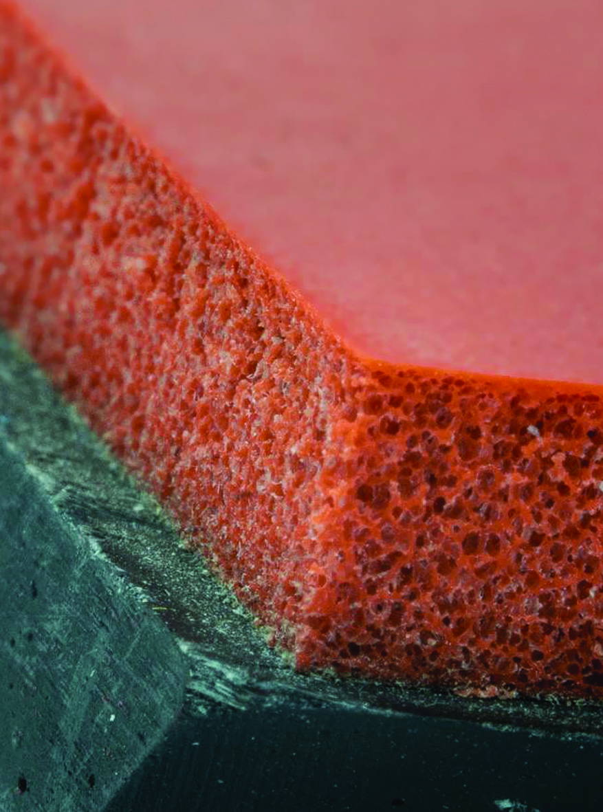
Photo 3: FRP Saddle and Closed Cell Gasket.
2.2.1 Construction and Placement
Factory-bonded to the SmartPad’s pipe side, the closed-cell elastomer compresses under band preload to form a continuous, conformal contact that accommodates normal surface roughness and remains uniform through thermal and vibration cycles at the pipe–pad interface.
2.2.2 Functions at the Pipe–Pad Interface
• Moisture Exclusion / CUPS Control: Very low water uptake; compressed contact suppresses crevice geometry and ion/oxygen transport, limiting crevice/under-deposit and MIC precursors.
• Vibration and Noise Attenuation: Viscoelastic damping lowers transmitted shear and micro-slip; the compliant, non-metallic layer acts as an acoustic impedance break to reduce structure-borne noise and alternating stress.
• Assists Galvanic Isolation: In combination with the FRP saddle, maintains a fully dielectric contact path.
2.2.3 Typical Material Properties
• Type: Closed-Cell Elastomer (e.g., silicone / EPDM)
• Density: 14–18 lb/ft³ (≈225–290 kg/m³)
• Compression-deflection @25% (ASTM D1056): ≈7.5 psi (≈52 kPa) [3]
• Hardness (ASTM D2240, Shore 00): 40–60
• Water absorption (ASTM D471): <0.1% by volume
• Operating temperature: –60°F to 570°F (-51°C to 300°C) • Compression-set resistance: Excellent
2.2.4 Durability and Integration
Under FRP-band preload, the gasket maintains stable compression, preserving seal and damping through thermal/vibration cycling and tolerating minor surface irregularities from prior repairs. Within the fully non-metallic load path, the gasket supplies sealing, compliance, and energy dissipation that complement the saddle’s stiffness and protect the coating at the pipe–pad interface.
2.3 SmartBands
2.3.1 Construction and Locking
Continuous long-strand FRP straps in a UV-resistant resin, paired with a matching-pitch FRP square-tooth buckle for incremental, non-backdrivable engagement. Radiused edges and smooth faces limit stress risers and coating damage.
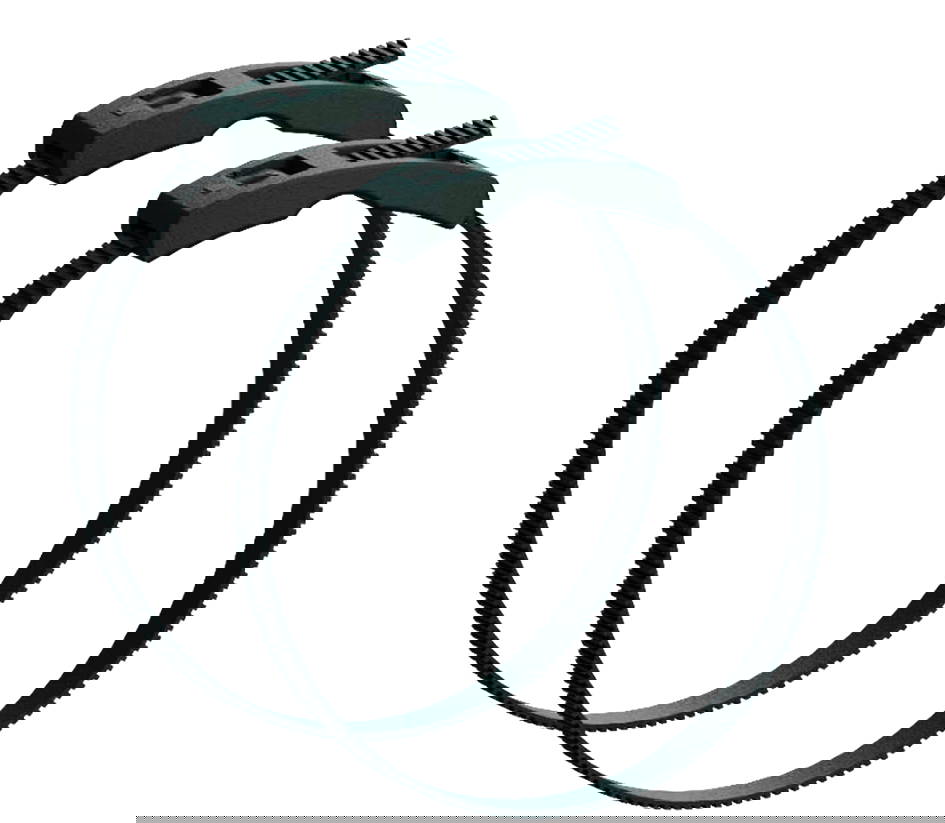
Photo 4: Non-Metallic Straps and Buckles.
2.3.2 Functions at the Pipe–Pad/Support Interface
• Dielectric clamping: All-composite load path preserves electrical isolation (avoids galvanic reintroduction).
• Preload delivery/retention: Long-strand reinforcement improves load transfer and creep/fatigue resistance, maintaining clamp force through thermal and vibration cycling.
• Surface compatibility / constructability: Non-marring inner face; smooth outer face for clean tensioning. Installs with a calibrated handheld tool—no hot work or adhesives.
2.3.3 Typical material properties
• Material: Continuous-strand FRP; UV-resistant resin.
• Tensile capacity (per band): ~1,200 lbf (≈5.3 kN).
• Thermal range: –40 °F to 250 °F (–40 °C to 121 °C).
• Electrical behaviour: Dielectric, non-metallic.
• Environmental durability: Corrosion-immune; outdoor/UV rated for coastal/offshore service.
2.3.4 Installation and Preload Control
Bands routed in moulded circumferential grooves in the saddle engage the FRP buckle and are tensioned to specification with a calibrated tool. Groove geometry sets bend radius, keeps the strap flush/recessed, and prevents lateral migration; the low-profile routing avoids snagging and maintains uniform bearing. Preload is confirmed by tool indication (or witness marks). For underside inspection, bands are single-use—they are cut and replaced with new bands; replacements are low-cost, and reinstallation typically takes minutes per support. Grooved routing also localises relative motion to the engineered slip plane at the saddle–support interface [4].
2.3.5 Durability and Integration
The continuous-strand architecture resists creep and tooth-root fatigue under cyclic loads. UV-stabilised resin supports long outdoor exposure; the all-composite assembly is unaffected by chloride corrosion. SmartBands provide the clamping force that maintains the Hydroseal seal and the saddle’s load-sharing contact within a fully non-metallic load path.
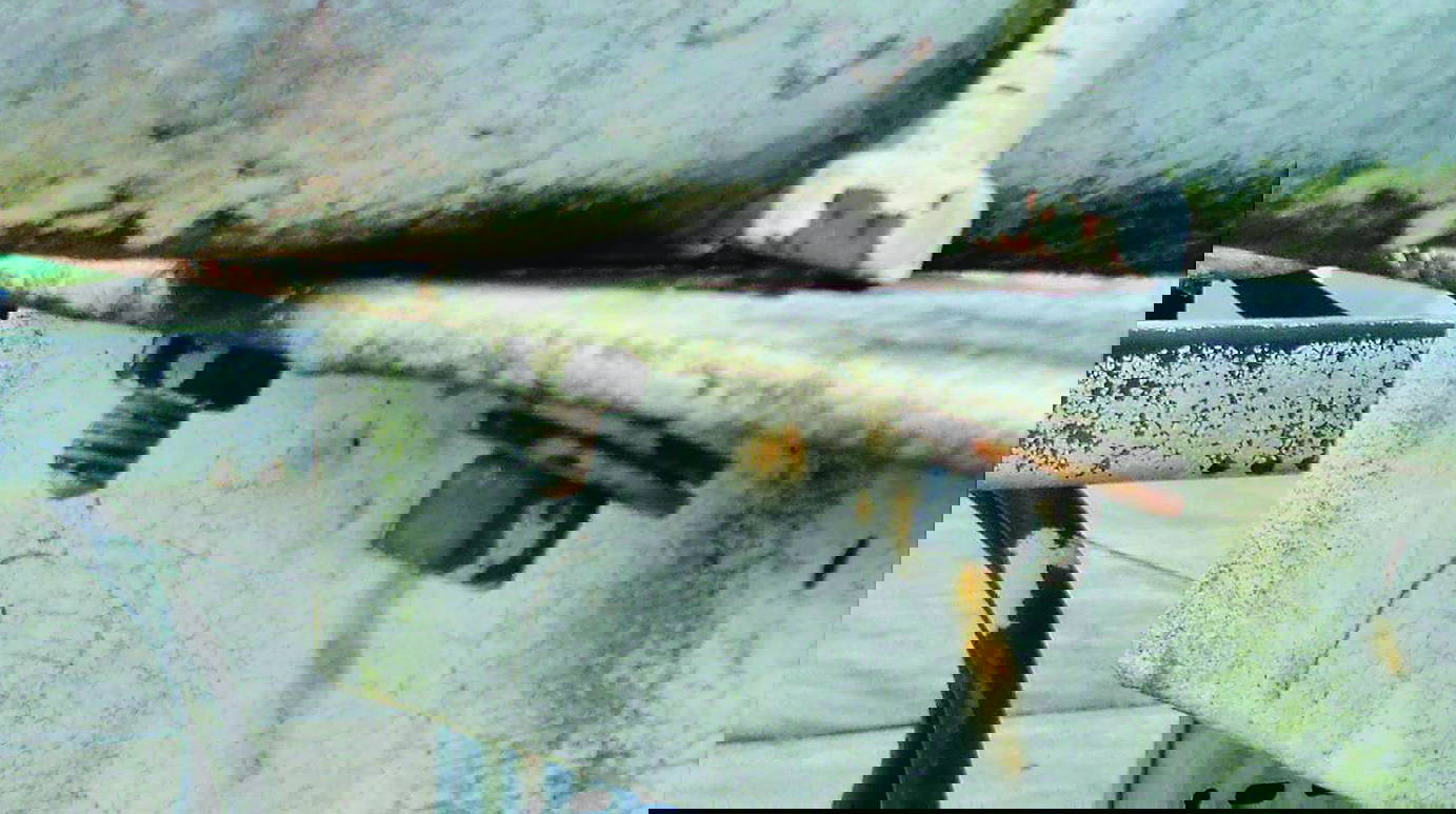
Photo 5: Example of Corrosion Under Pipe Support.
3. Corrosion Mechanisms at Support Interfaces
3.1 Crevice / Differential Aeration
Mechanism: A narrow, shielded gap at the pipe–pad interface traps a thin electrolyte. Oxygen is depleted inside the gap while adjacent surfaces remain aerated, creating an anode/cathode differential. Wet–dry cycling concentrates chlorides and lowers pH, undermining coatings and accelerating localised metal loss [1].
SmartPad Mitigation: A factory-bonded, closed-cell Hydroseal gasket forms a continuous conformal contact under preload, denying voids where films persist. The FRP saddle spreads load to keep contact pressure uniform through thermal cycles, disrupting the differential-aeration cell associated with CUPS.
3.2 Galvanic at the Support
• Mechanism: Electrically coupled dissimilar (or conditionally different) metals sharing an electrolyte drive anodic dissolution; small-anode/large-cathode area ratios intensify attack at supports [1].
• SmartPad Mitigation: A fully dielectric load path—FRP saddle, Hydroseal gasket, and FRP SmartBands™/buckles—breaks metal-to-metal continuity. The sealed interface also limits shared electrolyte, cutting off both prerequisites for galvanic corrosion.
3.3 Microbiologically Influenced Corrosion (MIC)
• Mechanism: In intermittently wet crevices, biofilms (e.g., SRB) create chemically distinct microenvironments (sulfides, acidity, differential aeration) that localise attack
[1]. • SmartPad Mitigation: The low-uptake, closed-cell contact shortens wet-film residence time and reduces attachment sites. Smooth, non-porous, electrically isolating surfaces further discourage biofilm establishment and persistence at the pipe–pad interface.
3.4 Fretting-Assisted Corrosion
• Mechanism: Sub-millimeter relative motion from vibration/thermal cycling abrades coatings and oxides; freshly exposed steel corrodes between slips, forming a wear–corrosion feedback loop focused at the supports [1].
• SmartPad Mitigation: Viscoelastic damping in Hydroseal stabilises the pipe–pad contact and lowers micro-slip. Required thermal movement is relocated to the low-friction saddle–support interface, while the FRP saddle’s load distribution reduces shear at the pipe wall.
3.5 Under-Deposit/Capillary Thin-Film
• Mechanism: Deposits or capillary-held films trap chloride-rich, oxygen-poor moisture that behaves like a crevice beneath the footprint [1].
• SmartPad Mitigation: The bonded, continuous interface leaves no seam for solids to wedge; closed-cell elastomer resists wicking. Moisture remains on exposed, cleanable surfaces rather than beneath the pipe.
4. Vibration
4.1 Sources and frequency content
Piping vibration originates from rotating/reciprocating equipment (pumps, compressors, blowers), pulsation in positive-displacement services, turbulence at fittings/reducers, two-phase/cavitation, hydraulic transients, alignment/soft-foot issues, and support stiffness mismatches. Field spectra commonly fall in the 10–100 Hz band with ~0.25–2.5 mm (0.01–0.10 in) peak-to-peak motion; response amplifies near span/support natural frequencies (cf. ISO 20816-1) [5].
4.2 Why the pipe–pad interface matters
Rigid, metal-to-metal load paths transmit dynamic energy as micro-slip and contact shear at the pipe–pad interface. This accelerates coating wear (promoting CUPS), excites support steel (structure- borne noise), loosens hardware, and increases alternating stress Δσ—shortening fatigue life per S–N behaviour.
4.3 SmartPad mitigation mechanisms
• Interface damping (Hydroseal). The closed-cell elastomer provides viscoelastic damping in the 10–100 Hz range, reducing transmitted shear/micro-slip and smoothing contact pressures [6].
• Relocated slip (FRP saddle). The moulded saddle furnishes a controlled, low-friction slip plane at the saddle–support interface so thermal movement does not abrade the coating at the pipe–pad interface; broad bearing further lowers work per cycle.
• Stable dielectric clamping (SmartBands™ in recessed grooves). Calibrated, all-composite preload maintains uniform contact without re-introducing metallic short circuits, low-profile routing resists lateral migration and secondary rattles.
5. Sound (Structure-Borne Noise)
5.1 Mechanism
Dynamic forces excite the pipe wall; a rigid, metal-to-metal path at the pipe–pad interface transmits that energy into support steel and deck members, which then radiate airborne noise. Frictional micro-slip at a hard contact can also generate “stick–slip” (squeal) components. Acoustic transmissibility rises when the interface impedance closely matches the supporting structure.
5.2 Sources and Frequency Content
The same drivers as vibration—rotating/reciprocating equipment, pulsation in positive-displacement (PD) services, turbulence, two-phase/cavitation, hydraulic transients, alignment/soft-foot, and support stiffness issues—dominate. On process/offshore lines, most structure-borne content is ~20–200 Hz, overlapping habitability and communication bands
[5]. 5.3 SmartPad Noise-Control Mechanisms
• Impedance break + damping (Hydroseal): The closed-cell elastomer introduces a compliant, non-metallic layer at the pipe–pad interface, lowering mechanical impedance and adding viscoelastic loss. Result: reduced transmissibility and less friction-generated noise from micro-slip.
• Controlled slip on the support side (FRP saddle): The moulded FRP surface provides a low-friction slip plane at the saddle–support interface, keeping relative motion off the coating and suppressing stick–slip at the pipe–pad contact. Broad bearing further lowers contact forces that drive radiation.
• Dielectric, Low-Profile Clamping (SmartBands in recessed grooves): All-composite bands maintain the decoupled path
(no metallic short-circuit) and sit flush to avoid secondary rattles; calibrated preload keeps contact uniform.
6. Structural Integrity (Fatigue & Stability)
6.1 Overview
The pipe–pad interface largely governs fatigue performance at supports. A hard, rigid contact concentrates routine loads and transmits vibration into repeatable stress cycles, leading to local denting, coating loss, misalignment, and ultimately crack initiation in the pipe wall or supporting steel [7].
6.2 Principal contributors at supports
• Thermal restraint. Limited slip forces the pipe to bear against the interface; daily temperature swings add alternating load.
• Small real contact area / edges. Narrow bearings or sharp transitions elevate local pressure and seed dents.
• Dynamic excitation. Equipment- and flow-induced vibration increases the stress range each cycle.
• Fit-up variability. Misalignment or uneven bearing amplifies local stress and accelerates coating abrasion.
6.3 Why this matters for fatigue
Fatigue life follows S–N behaviour and is controlled by the alternating stress amplitude (Δσ). Dents, coating scrapes, and other stress raisers reduce cycles to initiation; once the coating is breached, corrosion further degrades the section, compounding risk [7].
6.4 SmartPad mitigation mechanisms
• Load distribution — FRP saddle. Broad bearing lowers peak contact pressure and mitigates edge effects; the non-conductive substrate avoids metal-to-metal paths that undermine coatings.
• Compliance & damping — Hydroseal gasket. A firm, closed-cell elastomer equalises contact pressure, absorbs vibration, and cushions small impacts, reducing contact shear and Δσ per cycle [6].
• Controlled movement without abrasion — saddle–support slip plane. Thermal growth is taken on the moulded FRP surface (optional low-μ liner if needed), minimising stick–slip and fretting at the pipe–pad contact.
• Stable alignment & clamp — SmartBands in recessed grooves. Calibrated, all-composite preload keeps contact uniform and resists lateral migration; the dielectric, low-profile routing avoids galvanic short-circuits and loose hardware.
(For underside inspection, bands are single-use—cut and replaced; this is a low-cost operation).
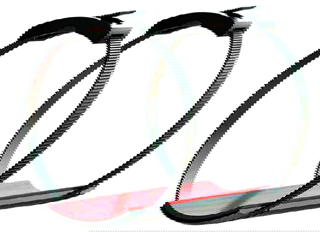
Photo 6: Full System Assembly.
7. Third-Party Testing: SmartPad Suitability for Industrial Service
Independent third-party testing was performed on specimens, as follows:
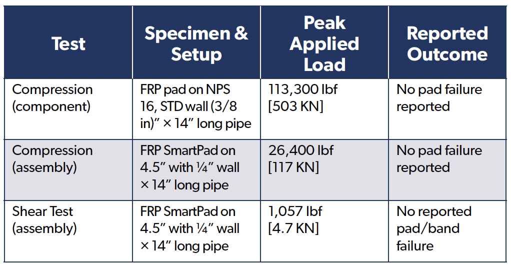
7.1 Results – Proof Loads, No Failures Observed
• Pad-only Compression: FRP saddle on NPS 16, STD wall pipe sustained 113,300 lbf axial compression without pad failure.
• Assembly Compression: Banded SmartPad-on-pipe (4.5 in OD × ¼ in wall) sustained 26,400 lbf axial compression without pad failure.
• Assembly Shear: Same assembly sustained 1,057 lbf lateral
(shear) without pad or band failure.
7.2 Interpretation
For the geometries/fixtures tested under monotonic loading, neither the composite saddle nor the banded assembly was the limiting element. The components tolerated high localised bearing and incidental lateral restraint typical of pipe-support reactions when installed and preloaded to specification.
7.3 Scope and Limits
These are static proof tests on short specimens. They do not establish design allowables or characterise fatigue, creep/relaxation, or environmental durability. Apply normal owner engineering practices (codes, load combinations, temperature, vibration/fatigue assessment) [8,9].
7.4 Implication for Use
Combined with the corrosion mechanisms described in section 3 (sealed dielectric interface, viscoelastic damping at the pipe–pad contact, and load spreading/controlled slip), the proofs support the SmartPad System’s mechanical suitability as a non-metallic pipe-support interface for industrial and offshore service, subject to project-specific engineering review.
8. Case Study — Coastal Texas Chemical Plant (Anonymised) Background
A large Gulf Coast complex retrofitted the RedLineIPS SmartPad System to mitigate CUPS, structure-borne noise, and nuisance vibration at pipe/support interfaces in a salt-laden, high-humidity environment.
8.1 Scope
• Units: Olefins recovery, utilities/cooling water, brine handling.
• Lines: Carbon-steel piping from 2”–24” NPS; cooling-water return, light condensate, brine.
• Quantity: ~5,000 supports installed during routine windows (no hot work).
• Configuration: FRP saddle + bonded Hydroseal closed-cell gasket + FRP SmartBands/buckles.
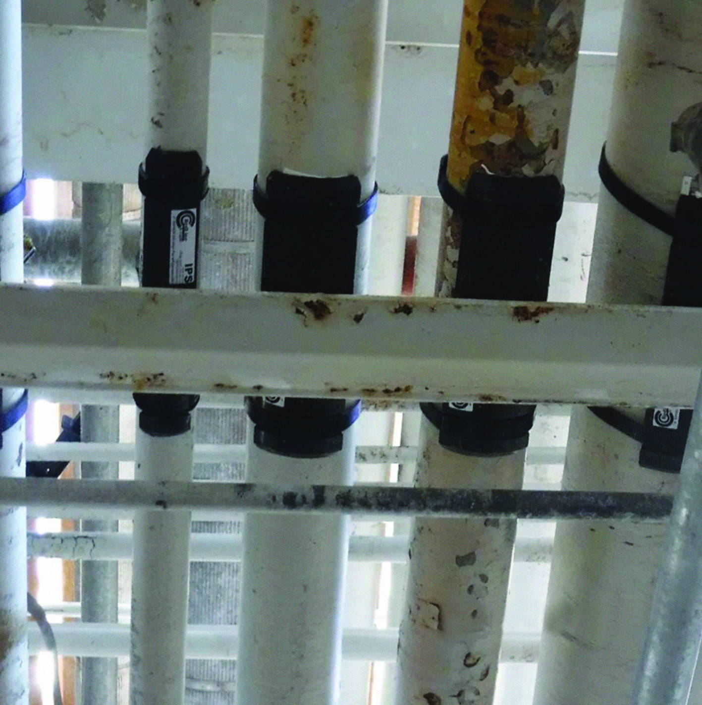
Photo 7: Installed System at Formosa Plant.
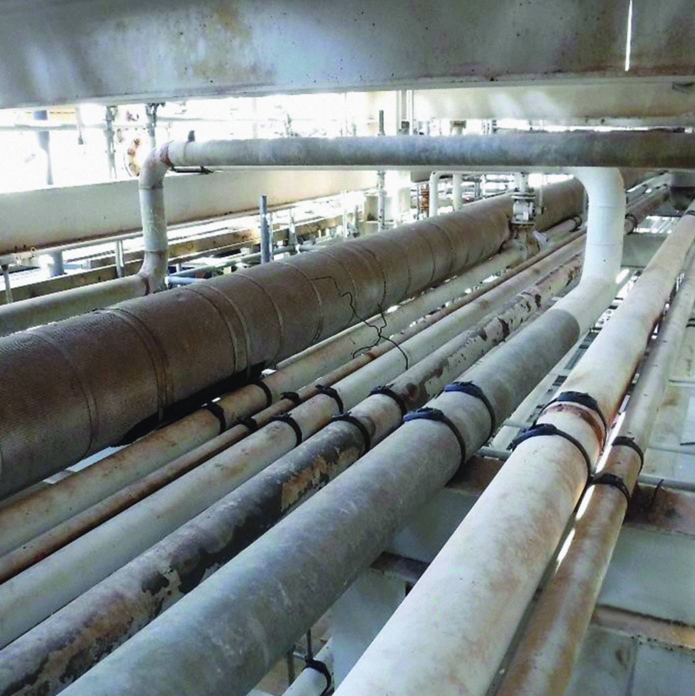
Photo 8: Installed System at Formosa Plant.