
Meet the Author
Dr Raghu Srinivasan is an Associate Professor and Chair of the Mechanical Engineering Department and Director of the Environmental Degradation Laboratory (EDL) at the University of Alaska Anchorage (UAA). He received his MS and PhD degrees in mechanical engineering at the University of Hawaii at Manoa in 2005 and 2010, respectively. Dr Srinivasan’s research focuses on atmospheric and marine corrosion, materials compatibility, and corrosion in oil and gas infrastructure, with a strong emphasis on Arctic and sub-Arctic environments. He currently serves as the Chair of the Research Society Leadership Council (RSLC, 2025–2027) and served as Vice-Chair of the Research Programme Committee (RPC, 2023–2025) for the Association for Materials Protection and Performance (AMPP). He has been recognised with multiple awards: UAA’s Chancellor Award for Research, the NACE Foundation Book Scholarship Award, the Harvey Herro Best Poster Award, the Materials Performance Corrosion Innovation of the Year Awards (2019 and 2023), and the NACE International Research Seed Grant (2019).
Introduction
Atmospheric corrosion is a complex process, which involves chemical, electrochemical, and physical changes to the metal exposed. Atmospheric corrosion occurs when a metal surface is under a thin layer of moisture, but not completely immersed, and the metal surface corrodes while exposed to environmental factors. The atmospheric corrosion damage in cold environments is close to the main human activity, which is concentrated near the coastal areas.
The substantial human growth and climate change in the Arctic and sub-Arctic region push for a renewed, better understanding of the atmospheric corrosion mechanisms that can lead to a good choice of materials selection and better design practices for infrastructure and other applications. This article describes the development of multi-angle corrosion test racks that were deployed at four test sites across Alaska, each distinct in their environment and equipped with weather sensors and chloride candles.
Atmospheric Corrosion in Cold Climates
The Arctic and sub-Arctic region identified by the U.S. Army Cold Regions Research and Engineering Laboratory (CRREL) [1] has an average temperature of -18°C or less during winter. The most common assumption is that there is very little to no corrosion in cold environments [2]. However, previous studies in the Antarctic and Arctic regions have disproved that notion, finding that corrosion rates are substantial [3-5]. The atmospheric corrosion damage in cold environments is close to the main human activity, which is concentrated near the coastal areas. Previous studies in the sub-arctic region of Canada, Norway, and Russia show extensive atmospheric corrosion rates (when compared to Antarctica) due to human developments and the resulting increase in mining and metallurgical industries [2]. Experimental and theoretical work has shown that the electrochemical process proceeds at temperatures as low as -25°C to -20°C [6-7].
Sereda measured the potential between platinum and zinc electrodes at -20°C, concluding that when an electrolyte is present, corrosion will proceed [6]. Moreover, very little corrosion data is available for metal alloys exposed to cold conditions. Studies by Divine and Perrigo [5] in Anchorage, Alaska; Biefer [8] in the
Canadian Arctic and sub-Arctic sites; Kucera et al. [9] in Scandinavia; and Mikhailov et al. [10] in eastern Siberia have shown corrosion rates of carbon steel close to the C1 category of the ISO 9223 classification (Table 1).
Table 1: One-Year Corrosion Rates and Corrosion Categories.
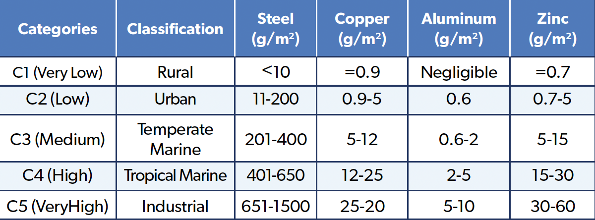
Even though the corrosion rates are lower than the C1 category, the substantial human growth and climate change in the Arctic and sub-Arctic region push that envelope. Because of this, there is a case to add a cold climate category to the classification. Factors that drive the atmospheric corrosion in cold climates are winds that can bring in salt-laden snow from the marine environment, and the use of de-icing salts can also contribute to high levels of chlorides [2]. The eutectic point, or the freezing point, of de-icing salts can be lowered to -50°C, melting the ice/snow layer on top of metal samples [7]. This phenomenon keeps metal samples moist for much longer periods, thus increasing the time of wetting (TOW).
In the presence of chlorides and moisture, extensive atmospheric corrosion damage can be observed on metal samples. Another contributing factor to high corrosion rates is low rainfall, which in turn cannot periodically wash off the deposited chlorides and SO2 on top of the samples [2]. In addition, ever-increasing ambient temperatures due to climate change in recent years affect the snow presence on top of the metal samples [11]. The temperature of the samples is not too high to evaporate the deposited snow/ice but high enough to cause melting and sustain moisture for longer periods of time. This leads to the formation of varying thicknesses of wet ice/snow layers on the metal surface. Long hours of sunlight in the summer also increase the surface temperature of metal samples beyond the ambient temperatures, causing dew formation and condensation, which in turn results in higher TOW.
Multi-Angle Test Rack Design
The design and methodology of atmospheric corrosion test racks have been guided by several pivotal standards over the years.
Prominently, the ASTM standard G50: “Standard Practice for Conducting Atmospheric Corrosion Tests on Metals,” and more particularly subsection five concerning exposure racks and frames, has served as an instrumental reference point for this research herein [12]. Similarly, ISO 8565, “Metals and alloys—Atmospheric corrosion testing—General requirements for field tests,” was another crucial standard consulted during the design process [13]. Over time, atmospheric corrosion test racks have seen iterative developments to address specific research requirements. Notable research endeavors that have trod a similar path include studies conducted in diverse geographies.These studies offer a comparative perspective and serve as benchmarks for the current investigation. A seminal study from 1995 introduced an atmospheric test rack design that facilitated specimen exposure across various orientations and angles [14].
Subsequently, a research team from the University of Hawaii devised the “Compact Octagonal-Prism Portable Exposure Rack” (COP-PER) to specifically assess the impact of wind direction and specimen orientation on corrosion rates [15]. Additionally, collaborative efforts from Spain and Portugal resulted in the development of a tree-shaped rack, designed to concurrently evaluate specimen orientation and exposure angle in atmospheric corrosion studies [16].
Traditional test racks used for atmospheric corrosion monitoring are often inadequate for Arctic deployment. They cannot withstand snow loads, high winds, or severe temperature swings. To address this, a modular and adjustable atmospheric corrosion test rack was designed, later patented in the United States as US 11,499,909 B2. The rack design includes adjustable exposure angles (0°, 30°, 45°), a modular aluminum frame, integrated sensors, and corrosion-resistant construction (Figure 1).
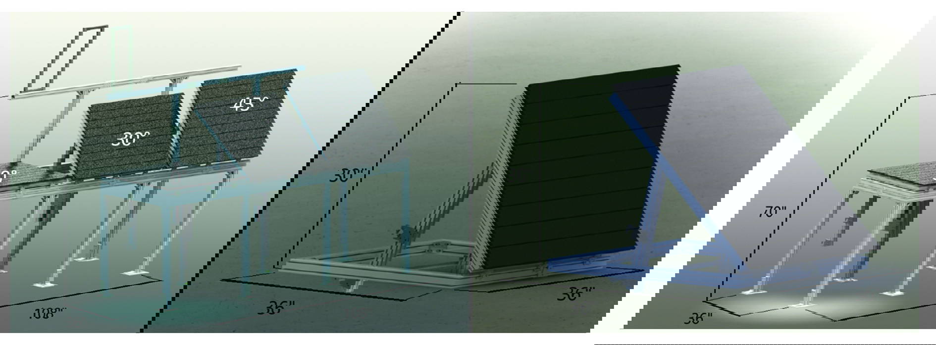
Figure 1: Adjustable Multi-Angle Corrosion Test Rack.
Atmospheric corrosion standards recommend an exposure angle of 30 degrees from the horizontal, facing south, and the lowest specimens be at least 30 inches above the ground. Time of wetness is one of the main parameters for atmospheric corrosion testing and can vary drastically depending on the angle of the exposed surface. This modular and adjustable corrosion test rack allows us to change the direction of exposure (north, south, east, or west) and the angle of exposure (0, 30, or 45 degrees to horizontal). These changes can be made easily and will save time when future adjustments are required for different exposure angles and directions. Lastly, this design can support a full weather monitoring system (Figure 2). These parameters include, but are not limited to, relative humidity (RH), ambient air temperature, TOW, rainfall, wind velocity, UV radiation, barometric pressure, and aerosol chloride and sulfate deposition.
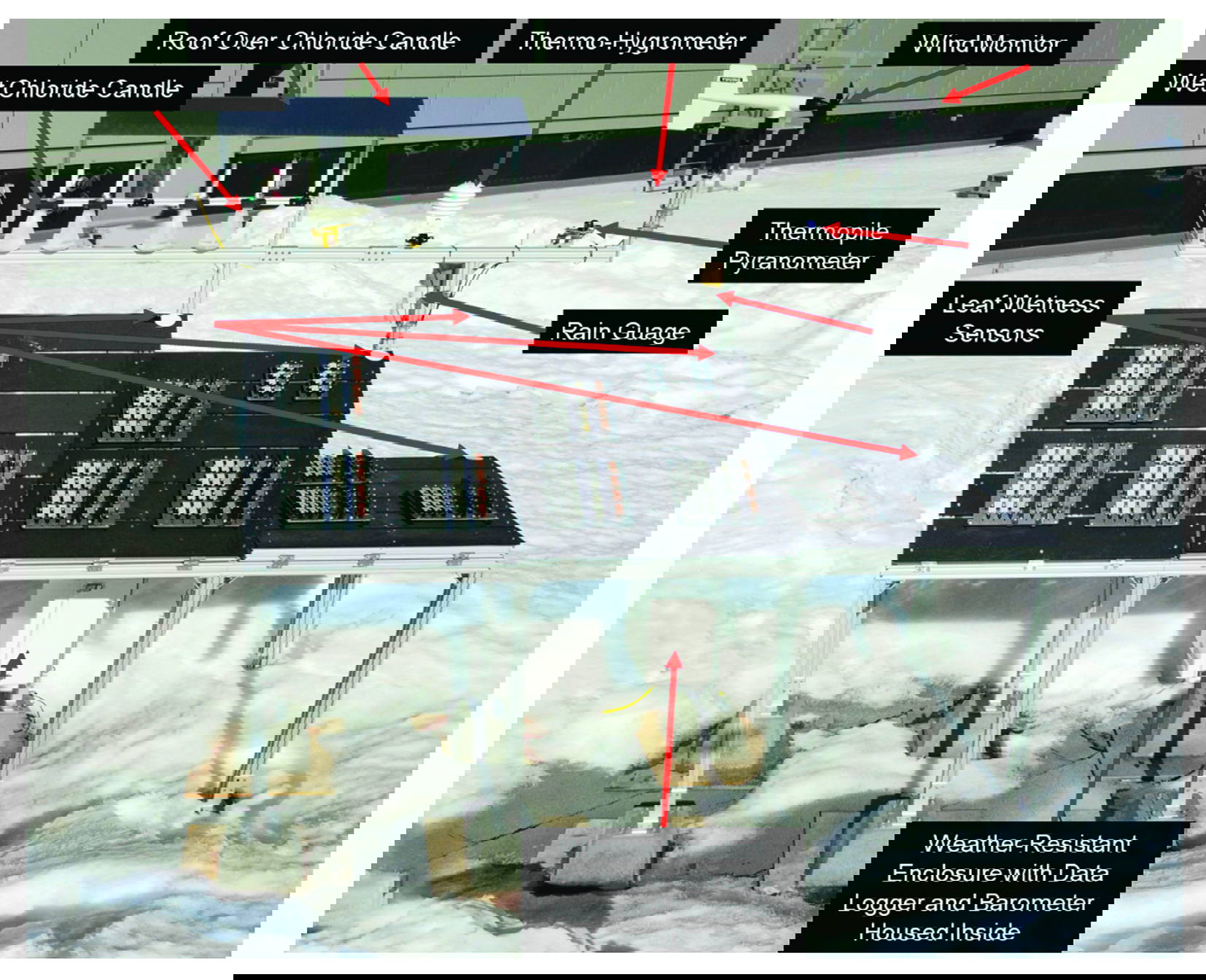
Figure 2: Multi-Angle Corrosion Rack with Auxiliary Weather Station.
Establishing Test Sites
Four strategic locations were selected as preliminary testing sites, with site selection and characterization heavily influenced by ASTM G92 “Standard Practice for Characterisation of Atmospheric Test Sites” [17]. Their positions can be referenced in Figure 3, which provides a map of Alaska.
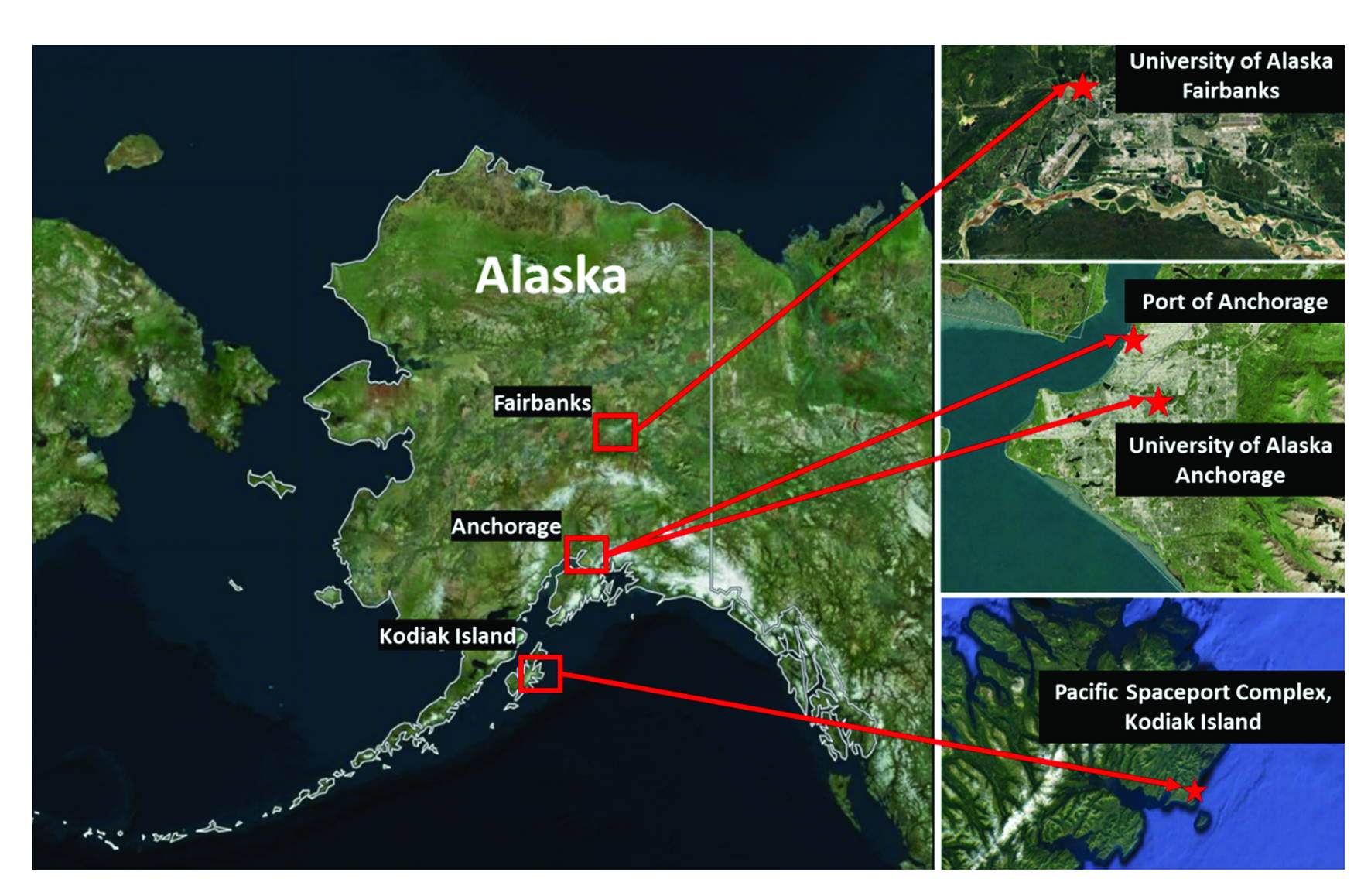
Figure 3: Map of Alaska Showing Four Corrosion Monitoring Sites.
Kodiak, AK – Pacific Spaceport Complex (PSCA) – Aggressive Marine Environment
Kodiak, AK, represents the aggressive marine environments commonly found along the southern and southeastern coastlines of Alaska. Coastal cities, such as Kodiak, receive on average a steady coastal breeze averaging 9 knots (4.6 m/s), average yearly precipitation of 65 inches (1651 mm), and average ambient temperatures of 41°F (5°C). This creates an aggressively corrosive
environment with relatively steady electrolyte exposure from rainfall and high relative humidity levels, as well as steady prevailing winds that provide high deposition rates of aerosol-borne Cl.
During the summer months, Kodiak experiences a maximum daily sunlight period of approximately 16 hours at the summer solstice and a minimum of 6.5 hours at the winter solstice. Both the summer and winter solstice are indicative of the maximum and minimum number of sunlight hours, respectively. This provides for periods of consistent solar irradiance exposure, which are maximized during the summers in Alaska. The exact exposure site is located in close proximity to the Pacific Spaceport Complex on Kodiak Island. Using pre-existing structures places the exposure rack ~5-6 feet elevated from the ground level and ~600 feet from the open ocean water.
Anchorage, AK – University of Alaska Anchorage (UAA) – Mild Marine Environment
Of the two exposure sites operated in Anchorage, AK, one resides at the University of Alaska Anchorage (UAA) and represents a very mild marine environment. Positioned 25 miles farther north than Kodiak, this site presents colder average temperatures and lower average precipitation rates comparatively. The average ambient temperature in Anchorage is 39°F (3.9°C) with an average precipitation of 16.9 in (430 mm). Both Anchorage sites typically exhibit lower average levels of relative humidity and receive lower Cl- deposition rates than those of Kodiak, but still experience these coastal effects, being only slightly offset from the shoreline.Anchorage sites receive longer periods of daily sunlight exposure, reaching upwards of 18.5 hours at the summer solstice and lowering to 5.5 hours at the winter solstice. This again provides generous solar irradiance exposure that is maximized during the summer months. At UAA, the particular exposure site is positioned on a building roof and is therefore elevated above the ground floor by ~30-45 feet. The site is also positioned much farther from the shoreline of the neighboring head of both the Knik and Turnagain Arm by ~4 miles. Where Kodiak is positioned far from any industrial or urban environment, UAA is positioned only a couple of miles from the downtown center. UAA is therefore more apt to be influenced by associated factors with urban areas, such as vehicle emissions and combustion byproducts, among others.
Anchorage, AK – Port of Alaska (POA) – Moderate Marine Environment/Mild Industrial Environment
The second of the two exposure sites, which operates in Anchorage, AK, resides at the Port of Alaska (POA, or “The Port”) and represents two environmental types with varying positions. Being situated similarly to the UAA site, all of the previous meteorological averages and data also apply to this site. The Port of Alaska handles the majority of fuel and freight cargo in Alaska, and it is an understatement that it is the lifeline of the Alaskan people. Its proximity to the ocean and constant truck movements make the Port of Alaska a strategic location to collect atmospheric corrosion data. In summary, upon inspection, the site presents a less corrosive environment than Kodiak does, with ample summer time solar irradiance exposure.
Fairbanks, AK – University of Alaska Fairbanks (UAF) – Inland Urban Environment
The last site is operated in Fairbanks, AK, at the University of Alaska Fairbanks (UAF), which best represents an inland urban environment. The summers are warmer than both Anchorage and Kodiak, with an average temperature of 60°F (15.6°C). However, the winters are much colder, with average winter temperatures of -4.3°F (-20°C). Average annual precipitation levels are the lowest of the four sites at 12.4 in (~315 mm). Fairbanks, being situated in a more northern location than Anchorage, receives exceptionally long periods of sunlight during the summer months, exceeding 21 hours at the summer solstice.
During winters, the inverse occurs with a mere 4 hours of sunlight at the winter solstice. This provides an incredibly large amount of solar irradiance exposure during the summer months relative to the other sites. Due to Alaska’s sheer size, Fairbanks lies approximately three hundred miles (~500 km) away from the nearest coastal area, which provides quite radical and unique weather challenges during the winter months. The particular site lies atop the Usibelli Engineering Building at approximately four stories, thus elevating the exposure rack ~60–72 feet above the ground floor.
While the exposure to airborne Cl- and SO4²- is expected to be considerably lower than at 28 Kodiak due to the relative positioning from open bodies of salt water, respectively, the UAF exposure site does typically experience an elevated exposure to airborne SO4²-. Interior Alaska is abundant in individual residential heating solutions for the winter months. The most common combustion sources include heating oil and wood. Both produce either primary or secondary SO4²- within the atmosphere, with primary SO4²- generally making up the most significant percentages. Fairbanks’ geographical characteristics are also highly conducive to frequent temperature inversions during winter. Temperature inversions most often cause cold air masses to settle beneath larger warm air masses. In effect, this traps any and all airborne contaminants within the lower-lying cold air masses. Trapped contaminants then have a longer period and a chance to deposit on the sample surfaces. Additionally, UAF also sits across the street from the University Power Plant. Table 2 gives a detailed layout of each test location and geographical coordinates.
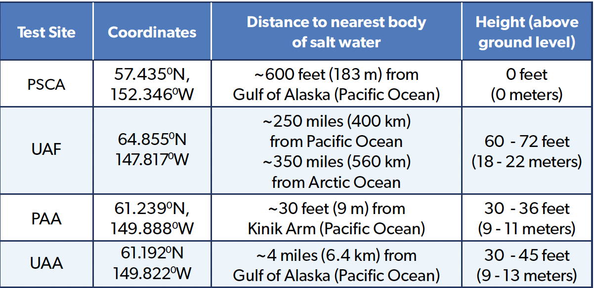
Table 2: Test Sites’ Coordinates, Distance From Sea, and Elevation.
Some Notable Results and Trends
Figure 4 delineates the ambient air temperature at the PSCA site, which, during the winter months, dips below the freezing mark on several instances and occasionally falls beneath -5°C. Despite these sporadic plunges, the overall trend captured by the solid red line indicates that the ambient air temperature stays above 0°C throughout the entire year-long exposure period, with the mean average, illustrated by the dotted red line, stabilising around 6°C. The PSCA’s proximity to the Pacific Ocean, a mere 600 feet away, confers a stabilising effect on its air temperature, moderating the extremes that might otherwise be observed. The climatic profile of Fairbanks, Alaska, is characterised by its starkly contrasting temperatures, with intense cold in the winter and, unexpectedly, notable warmth in the summer. As depicted in Figure 5, the ambient air temperature at the UAF site plummets to a frigid -35°C in December 2022 and soars to 28°C by late June 2022.

Figure 4: Ambient Air Temperature at PSCA – Raw vs Averaged Data. Figure 5: Ambient Air Temperature at Fairbanks – Raw vs Averaged Data.
Table 3 shows the calculated chloride and sulfate deposition rates for each test site over each exposure. The PSCA site has four to seven times the amount of chlorides when compared to UAF and UAA, the PAA test sites. Figure 6 depicts the corrosion rates for 1008 carbon steel (UNS G10080) for a 12-month exposure period. The carbon steel samples at the PSCA site exhibited corrosion rates at least four times greater than the carbon steel samples exposed at UAF, PAA, and UAA.
This can be attributed to the weather data, where PSCA recorded at least four times the amount of chloride deposition, and the samples spent at least 18% more time wet through all sites and exposures. At the PSCA site, a distinct correlation was observed between the exposure angle and corrosion rate. Samples exposed at 0° showed the highest corrosion rates, followed by those at 30°, with the lowest rates seen at 45°. The TOW data indicates that the 0° angle samples remained wet for longer periods compared to 30° and 45°. Although the other sites – UAF, PAA, and UAA – exhibited less pronounced trends and experienced four times less corrosion than PSCA, the samples at 0° consistently showed higher corrosion rates than those at 30° and 45°.
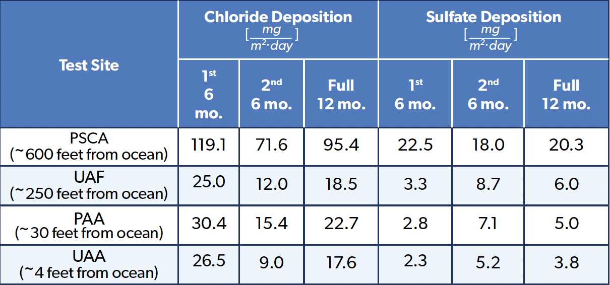
Table 3: Chloride and Sulfate Deposition Rates.
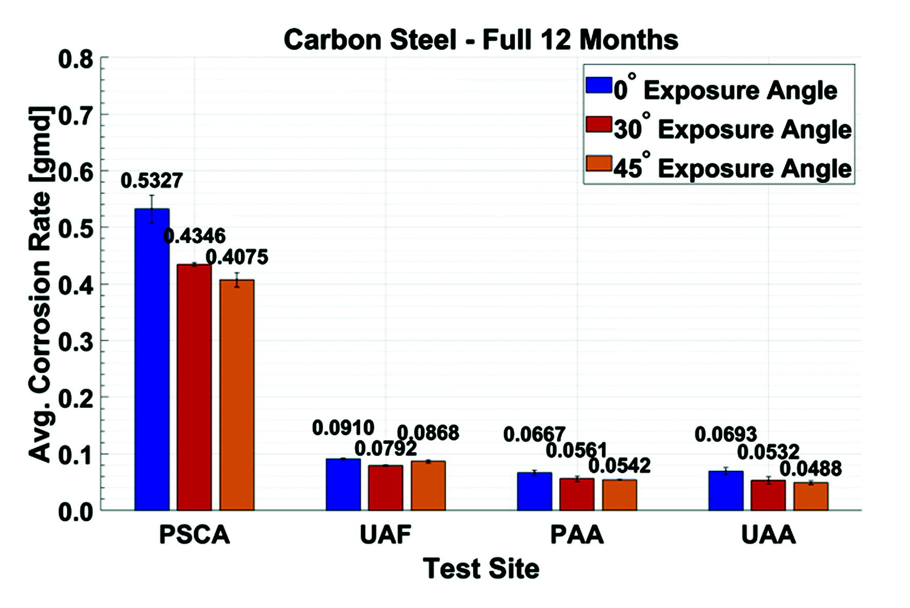
Figure 6: Average Corrosion Rates of 1008 Carbon Steel Over Full 12-Month Exposure Period.
Corrosion Rate Conversion
The following table is useful to put the above corrosion rates into context for the four test regions above.
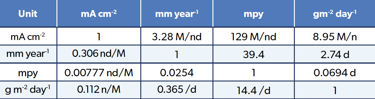
Table 4: Corrosion Rate Conversion.
Conclusion
New and innovative multi-angle corrosion test racks, each with auxiliary weather stations, were established at four test sites spanning across Alaska, USA. Each of Alaska’s four test sites presents a distinct corrosion profile: Kodiak (PSCA) exhibits high chloride-driven corrosion, Anchorage (PAA/UAA) faces freeze-thaw cycles with de-icing salts, and Fairbanks (UAF) experiences frost-dew cycling. Initial field campaigns revealed a clear correlation between exposure angle and corrosion rate. The combination of urbanisation and proximity to marine environments makes Arctic and sub-Arctic regions in North America, particularly Alaska, an important natural laboratory to study atmospheric corrosion in cold regions and the development of predictive models and corrosivity maps tailored for Arctic conditions. The fundamental knowledge of studying the basic atmospheric corrosion mechanisms in extreme cold conditions will result in better design practices for the built environment in the changing Arctic.
Acknowledgements
The author acknowledges the UAA’s College of Engineering and ConocoPhillips Arctic Science and Engineering Endowment, NASA EPSCoR CAN grant, and the many undergraduate students and collaborators who contributed to the design, installation, and operation of the corrosion monitoring sites across Alaska. Special thanks to graduate students Mr Tyler Cushman, Mr Jozef Huner, Mr Lawrence Giron Jr., Mr. Jacob Bodolosky, and machinist Mr Corbin Rowe. The author also gratefully acknowledges the organizations that provided access and site space for test rack installation, including the Pacific Spaceport Complex–Alaska (Kodiak), the Port of Alaska, the University of Alaska Anchorage, and the University of Alaska Fairbanks.
References
- E A Wright, CRREL’s First 25 Years: 1961–1986, US Army Cold Regions Research and Engineering Laboratory, Hanover, NH, 1986.
- Revie Winston (2000) Uhlig Corrosion Handbook, 2nd Edition.New York: John Wiley & Sons, Inc
- ASTM Committee G1 “Corrosiveness of Various Atmospheric Test Sites as Measured by Specimens of Steel and Zinc,”in Metal Corrosion in the Atmosphere, ASTM STP 435, American Society for Testing and Materials, Philadelphia, PA, 1968, 360–391.
- A Pearce and C G Smith, The Hutchinson World Weather Guide, Hutchinson, London, 1984.
- J R Divine and L D Perrigo, “Atmospheric corrosion testing in the arcticand subarctic—a review,” Paper No. 389, in Proceedings of the Corrosion 86 Conference, NACE, Houston, TX, 1986.
- P Sereda, “Weather Factors Affecting Corrosion of Metals,” in Corrosion in Natural Environments. ASTMSTP 558, American Society for Testing and Materials, Philadelphia, PA, 1974, pp. 7–22.
- G W Brass, “Freezing depression by common salts: implications for corrosion in cold climates,” in Proceedings of the National Association of Corrosion Engineers, Canadian Region Western Conference, Anchorage, Alaska, 1996, pp. 447–453.
- G A Biefer, Perform., 20(1), 16 (Jan. 1981).
- V Kucera et , “Corrosion of Steel and Zinc in Scandinavia with Respect to the Classification of the Corrosivity of Atmospheres,” in S.W. Dean and S. Lee (Eds.), Degradation of Metals in the Atmosphere, ASTM STP 965, American Society for Testing and Materials, Philadelphia, PA, 1988, pp. 264–281.
- A Mikhailov, M Syloeva, and E Vasilieva, Data Base on Atmospheric Corrosivity in Towns and Industrial Centres in the Territory of the Former USSR, Institute of Physics and Chemistry, Russian Academy of Science, Moscow,
- A A Mikhailov, P V Strekalov, and Yu M Panchenko, “Atmospheric corrosion of metals in regions of cold and extremely cold climate (a review)”, Protection of Metals, 2008.
- ASTM G50, “Standard Practice for Conducting Atmospheric Corrosion Tests on Metals,” ASTM International, doi: 10.1520/G0050-20.
- ISO 8565, “Metals and Alloys. Atmospheric Corrosion Testing. General Requirements,” BSI Standards Limited, 2011.
- Coburn, M Komp, and S. Lore, “Atmospheric Corrosion Rates of Weathering Steels at Test Sites in the Eastern United States — Effect of Environment and Test-Panel Orientation,” in Atmospheric Corrosion, 100 Barr Harbor Drive, PO Box C700, West Conshohocken, PA 19428-2959: ASTM International, 1995, pp. 101-101–13.
- L H Hihara, J Kealoha, and N Das, “Studying the effect of wind direction and specimen orientation on the corrosion of 1018 steel using a compact octagonal prism portable exposure rack,” NACE, 2019.
- J J Santana, et , “The influence of test-panel orientation and exposure angle on the corrosion rate of carbon steel. mathematical modelling,” Metals (Basel), vol. 10, no. 2, p. 196, Jan. 2020.
- ASTM G92, “Standard Practice for Characterisation of Atmospheric Test Sites,” ASTM International, 2020.