What Stops the Reinforcing Steel in Damp, Porous Concrete from Corroding (Usually)?
John Broomfield, Corrosion Engineering Solutions Ltd.
Meet the Author
John Broomfield
John Broomfield is a Fellow of ICorr, AMPP, and the Concrete Society. He is a Chartered Materials Engineer and Chartered Scientist. He is also a Level IV Senior Cathodic Protection Engineer and an AMPP/NACE International Corrosion Specialist. He has over 40 years of experience in dealing with deterioration and durability problems in the built infrastructure, specialising in reinforced concrete, corrosion of steel-framed structures, and conservation of historic buildings and monuments. He has worked on projects all over the world and undertaken condition surveys, repair feasibility studies, life cycle cost analysis, corrosion risk analysis, repair specification, and repair design. He specialises in the application of electrochemical techniques for the investigation, rehabilitation, and design of durable new construction.
Concrete
Concrete has been used for millennia in various forms, principally as unreinforced mass concrete. The Romans used a form based on volcanic ash extensively, one of the finest remaining examples being the Pantheon in Rome.
The development of Portland cement by Joseph Aspdin in the early 1800s using simple, widely available materials and then the development of reinforced concrete by François Hennebique in the late 1800s led to the development and use of reinforced concrete for buildings, bridges, and other major structures. There had been attempts to use other metals to reinforce concrete, but iron and steel turned out to be the most compatible due to the similarity of their thermal expansion coefficients [1].
Concrete is a composite of cement powder and water mixed with coarse and fine aggregates. It is the cement that binds the aggregates together as it hydrates. The most common binder is Portland cement, made from limestone and clay roasted and ground in a kiln. It is a complex mixture of calcium compounds such as silicates, aluminates, and iron oxides that, when combined with water, form a calcium silicate hydrate gel that binds the concrete mix together. The hydration process, when completed, leaves a level of porosity in the hardened concrete of the order of 10%. These pores contain calcium hydroxide both in solution and as a precipitate, along with some sodium and potassium oxides/hydroxides.
While strong in compression, concrete is weak in tension, requiring reinforcement in many applications. Steel exposed to water and oxygen will oxidise unless effectively starved of oxygen or completely dried out. Absence of water in concrete can occur in indoor environments or behind external cladding. Absence of oxygen can occur in submerged concrete. For normal outdoor exposure, the steel would be subject to corrosion at a rate that would be harmful over the lifetime of a structure due to the ingress of water and oxygen through the pore system unless otherwise protected.
Corrosion Resistance of Reinforcement
Fortunately, the excess calcium hydroxide in the concrete pores, combined with some sodium and potassium hydroxides, elevates the alkalinity at the steel surface to around pH 12.5 to pH13. At this point in the Pourbaix diagram [2], iron is passivated, forming a thin, protective, self-sustaining oxide layer with a very low corrosion rate. As long as the concrete cover to the steel remains intact, sufficiently alkaline, and uncontaminated, the steel will remain in good condition despite the presence of oxygen and water at the concrete and steel surfaces, or perhaps we should say that the protection of the steel is because of the presence of oxygen and water to maintain the protective passive oxide film. We therefore have reinforced concrete structures that can last 100 years or more without showing any signs of reinforcement corrosion.
A true passive layer is a very dense, thin layer of oxide that leads to a very slow rate of oxidation (corrosion). There is some discussion as to whether or not the layer on the steel is a true passive layer. It seems to be thick compared with other passive layers and it consists of more than just metal oxides but, as it behaves like a passive layer, it is generally referred to as such.
Corrosion scientists and engineers spend much of their time trying to find ways of stopping the corrosion of steel by applying protective coatings to steel. Metals such as zinc and polymers such as acrylics or epoxies are used to stop corrosive conditions from forming on steel surfaces. The passive layer is the corrosion engineer’s dream coating, as it forms itself and will maintain and repair itself as long as the passivating (alkaline) environment is maintained.
Factors that Accelerate Corrosion in Reinforcement
However, the passivating environment is not always maintained. For reinforced concrete in normal atmospheric exposure, two conditions can break down the passivating environment without attacking and destroying the concrete itself. One process is carbonation, and the other is chloride attack.
Carbonation occurs when the naturally occurring carbon dioxide (CO2) in the air reacts with the alkaline oxides/hydroxides in the concrete pore water. The dissolution of CO2 in water forms carbonic acid, a weak acid that does not attack the cement paste or the aggregates in the concrete but reduces the pore water pH below 10. At that point, the passive layer on the steel breaks down, and the steel is vulnerable to corrosion. Carbonation moves as a front through the concrete cover. The rate of progress of the carbonation front is approximated by a simple diffusion equation where the depth of carbonation x at time t after construction is given by:
x = kt1⁄2
Where k is a constant. The carbonation front is a transition in pH from about 12.5 to 8.5 and is a few millimetres wide. The depth of carbonation can be measured using an indicator solution, sprayed on to a freshly exposed profile through the cover concrete. An example is shown in Figure 1.
Right: Figure1: Phenolphthalein Indicator Applied to Freshly Broken Concrete to Measure the Carbonation Depth on a Reinforced Concrete Window Mullion.
The other condition leading to the de-passivation of steel is exposure to chloride ions (Cl-), generally from sea salt or de-icing salts. In this case, the chlorides diffuse into the concrete and build up in the concrete cover until there is sufficient concentration at the steel surface to break down the passive layer. There is no moving front, but there is a threshold for corrosion at the steel surface when the chloride ions successfully compete with the hydroxyl ions and break down the passive layer. The threshold is generally taken as being in the range of 0.2 to 0.4% chloride by mass of cement for low-alloy carbon steels in Portland cement- based concretes. It should be noted that for the newer “low carbon concretes,” the threshold has yet to be confirmed and may reduce with age [3].
Once the steel is de-passivated by carbonation or by chlorides, reinforcement in atmospherically exposed concrete will start to corrode. The most common corrosion process forms porous iron oxides with a volume several times that of the steel consumed. This leads to tensile forces which will crack and delaminate the concrete cover [4]. There are field techniques for measuring the carbonation depth in concrete and for sampling for chlorides. There are also non-destructive techniques for estimating the corrosion condition. Reference electrode potential measurements can identify areas of actively corroding steel and a polarisation resistance kit can estimate the corrosion rate [4,5].
Remedial Measures for Corrosion in Concrete
There are a range of techniques for preserving and restoring the passive layer on steel. These include the application of coatings, physical repair of the concrete, and a range of electrochemical techniques. Coatings are preferred for preventing the ingress of chlorides and CO2. BSEN 1504-2 [6] gives details on the selection and performance of anti-carbonation coatings and of penetrating sealers that resist chloride ingress. It has been found that anti- carbonation coatings are effective in controlling the corrosion rate in carbonated concrete by controlling moisture ingress as well as CO2 [7]. However, penetrating sealers applied to chloride contaminated concrete are less effective in slowing corrosion once the corrosion threshold chloride concentration has been exceeded at the steel surface.Electrochemical techniques such as re-alkalisation, chloride extraction, impressed current and galvanic cathodic protection are all effective in preventing corrosion of the steel, regardless of the extent of de-passivation if used appropriately [4].
Corrosion in Alternative Types of Concrete
It is important to recognise that the concrete cover to the steel must sustain the passive layer throughout the life of the structure if there is a corrosion risk. The performance of Portland cement concrete, and concretes with blended cements is well understood. However, there is now a new range of low-carbon cements being made available to the construction industry. In a recent article in CM [3], I expressed concern about the long-term corrosion protection afforded to low-alloy steel reinforcement by novel cement materials. Are there sufficient alkali reserves available over 50 to 100 year design lives to ensure the steel cannot corrode? Is anyone testing them? The recent problems with reinforced autoclaved aerated concrete (RAAC) are also interesting. RAAC is a very low-density concrete with minimal resistance to the ingress of water and CO2. It was designed for ease of handling and low cost. Much of the press-coverage around this issue is confused. RAAC has many problems and failure mechanisms and many are not corrosion related. These problems include poor placement of reinforcement, poor placement of units [bearing shelves], deterioration through wetting & drying cycles and negligible to zero cover to the reinforcement. However, RAAC was supposed to be used in a dry, indoor environment where the corrosion risk to the reinforcement is minimal. RAAC beams were often installed under flat roofing. Any leaks would expose the concrete to wetting and drying, which would allow rapid carbonation and rapid breakdown of the passive layer with subsequent reinforcement corrosion. Flat roofs have a limited life, and identifying leakage can be difficult, especially above false ceilings. The problems were foreseeable and were foreseen by many, but not necessarily always by those with the responsibility and budgets for keeping the buildings safe. Moreover, this is not just a corrosion issue or a failing of the material – if your roof is leaking, you have bigger problems than just how it might affect any RAAC that might be present.
Summary
We can therefore see that the alkaline reserves in the concrete pore water leads to the formation and maintenance of the protective passive layer on the reinforcing steel. This is crucial to the durability of steel-reinforced concrete exposed to normal atmospheric conditions. Those responsible for the maintenance of reinforced concrete structures need to understand how and why reinforcing steel is protected from corrosion. If corrosion occurs, the correct techniques must be used to assess the cause and extent of the problem and the correct treatment applied to control corrosion and maintain the asset for the required life.
References
Paul Lambert Reinforced Concrete: The History, Properties and Durability of Reinforced Concrete , Technical Note 1 Corrosion Prevention Association, Bordon Hants, 2018.
Pourbaix, M. (1974). “Applications of Electrochemistry in Corrosion Science and in Practice.” Corrosion Science Vol. 14: p. 25-82.
Broomfield, J.P The Corrosion Resistant Properties of Novel Cements, Concretes, and Reinforcement, Corrosion |Management July/Aug 2023 pp 22-23.
John Broomfield, Corrosion of steel in concrete, 3rd edition Publ. CRC Press, London, 2023.
Concrete Society Technical Report 60, Electrochemical Tests for Reinforced Concrete. Concrete Society, Camberley, 2004.
BS EN 1504-2 (2004) Products and Systems for the Protection and Repair of Concrete Structures – Definitions, Requirements, Quality Control and Evaluation of Conformity: Part 2: Surface Protection Systems for Concrete.
Seneviratne, A. M. G., Sergi, G. Page, C.L. (2000). “Performance characteristics of surface coatings applied to concrete for control of reinforcement corrosion.” Construction and Building Materials 14: 55-59.
Question:
Why are coatings often supplemented with cathodic protection to protect against corrosion?
Answer:
Corrosion is one of the most critical failure mechanisms in structures, installations, components, and mechanical systems, in which materials go through decay or deterioration, which in turn compromises the integrity of these structures or systems. Deterioration is the cause of the formation of oxides, hydroxides, or sulphides, which are naturally more stable forms of any refined material. There are several reasons for corrosion to initiate and propagate, these include environmental and operational conditions, material properties, and electrochemical activation. Although several factors are involved in initiating and propagating corrosion, a key factor is the availability of an active metal surface, which incubates electrochemical changes leading to corrosion.
Therefore, the primary focus, as a cost effective, efficient, and reliable technique, is to convert the active metal surface areas into passive surface areas. This helps stop or decelerate corrosion, and can be done by providing a protective current, which in turn reduces the potential of a metal surface. This results in cathodic protection, hence stopping or significantly reducing electrochemical changes, in other words, any corrosive attack is halted. There are two conventional methods by which passivation of metal surfaces is achieved. These are commonly known as (i) sacrificial anode cathodic protection, and (ii) impressed current cathodic protection. The above methods have been widely used in several industrial applications, such as petrochemical, marine, and infrastructure. Another effective technique for mitigating corrosion is to use a coating. The coating acts as an anti-corrosive protective layer, a barrier, or a sacrificial layer over the metal. Coatings offer several benefits by protecting materials, enhancing surface characteristics, and avoiding or reducing the risks of failure. Corrosion, however, becomes more complex in terms of its failure mechanisms when structures and components are dynamically loaded as in marine structures. This will cause failures such as corrosion fatigue and stress corrosion cracking.
Or when static structures are exposed to more aggressive environments, corrosion and corrosion failures will significantly accelerate. The combination of both coatings and cathodic protection will enhance metal resistance against corrosion. Therefore, a combination of both is widely used. These preventative methods also assist at the design stage in reducing the required weight of material for required operating lifetime and can thus significantly reduce fabrication and later transport costs with net-zero type benefits.
A more complex corrosion mechanism will occur when components are dynamically loaded and are subject to relative motion. This adds more complexity to attempts at stopping or controlling corrosion, because other mechanical and physical factors are now combined and are contributing to a more complex form of deterioration. In such instances, the use or application of cathodic protection becomes complicated, challenging, and in some cases, it becomes almost impossible to meet specified CP criteria. Therefore, more robust methods of enhancing corrosion resistance through material development, advanced coatings and coating techniques, corrosion monitoring, and prognostic measures, have been developed over the past several years. It is more pragmatic to provide bespoke solutions for specific applications.
If the components are interacting, then surface wear will occur. In a scenario where corrosion is absent, the wear purely results from mechanical loading and surface deterioration. However, in the presence of corrosive species, corrosion will also occur. This leads to a wear-corrosion mechanism.
Recent Coating Developments
Researchers have been developing advanced coatings to withstand both corrosion and wear in challenging and harsh environmental and operational conditions subject to design life requirements. Recent developments in nanocoatings and nanocomposite coatings [5], have shown that more attractive coating solutions are available for applications in more complex mechanical and chemical conditions. These nanocomposite coatings are, for example, Ni/Al2O3, Ni/SiC, Ni/ZrO2, Ni/Graphene (GPL), and several others. Such coatings have been developed in order to be subjected to corrosion while incorporating the effects of key mechanical properties. These newly developed nanocomposite coatings have been tested according to ASTM B117,
salt spray testing [1].
Further study of the above nanocomposite coatings has been conducted within the wear context [2].
A comprehensive study of the above nanocoatings at atomic surface layers, incorporating corrosive fluids, and using a numerical approach, was conducted [3].
It is well known that the durability and reliability of complex interacting systems are very important from a cost viewpoint and within a wider sustainability context. These interacting systems are subject to corrosion failures and are therefore a major concern for industry professionals. It is important to fully diversify design parameters.
Remote Monitoring
Further work has been performed to predict corrosion in dynamically corrosive environments by considering physical and mechanical characteristics. Researchers have recently developed and patented a new corrosion sensor that could improve the safety and reliability of large structures such as bridges, aircraft, military vehicles, and gas pipelines. The device can detect defects and risks in major infrastructure at a much earlier stage than the methods that are currently used. As well as improving safety, it could reduce the need for time consuming repairs, which can come at a significant cost and inconvenience to industries and the public.
In summary, it evident that the primary objective of an industrial coating is to prevent corrosion, and to withstand a variety of hazardous chemicals. Choosing the right coating is just as important as choosing the coating itself, a wrongly specified coating can lead to a wide range of problems, from maintenance to premature failure. No coating is completely free of defects, even when freshly applied. Faults can occur during the production of the coating as well as during handling and improper application of the coating. A defect may also arise during the course of service. The most common causes of coating failures include inadequate surface preparation, a non-friendly environment, poor formulation, and an inefficient application technique. Coatings with high efficiency are more expensive. Thicker coatings, the use of sophisticated inspection methods, and fixing specific defects, all result in higher cost and critically weight. Sometimes it is advantageous to use another protection method to supplement coatings, which is why we use cathodic protection and especially in marine situations. There is an overall benefit when a good coating application is combined with cathodic protection [4].
Prof. Zulfiqar Khan, Bournemouth University NanoCorr, Energy & Modelling (NCEM) Research Group.
References
1. Nazir, M.H., Khan, Z.A., Saeed, A., Bakolas, V., Braun, W., Bajwa, R. and Rafique, S., 2017. Analyzing and modelling the corrosion behavior of Ni/Al2O3, Ni/SiC, Ni/ZrO2 and Ni/graphene nanocomposite coatings. Materials, 10 (11).
2. Nazir, M.H., Khan, Z.A., Saeed, A., Bakolas, V., Braun, W. and Bajwa, R., 2018. Experimental analysis and modelling for reciprocating wear behaviour of nanocomposite coatings. Wear, 416-417, 89-102.
3. Nazir, M.H., Khan, Z.A., Saeed, A., Siddaiah, A. and Menezes, P.L., 2018. Synergistic wear-corrosion analysis and modelling of nanocomposite coatings. Tribology International, 121, 30-44.
4. L.L. Sheir, R.A. Jarman, and G.T. Burstein; “Corrosion”, Volume 2: “Corrosion Control”, 3rd edition, Butterworth Heinemann, ISBN 0-7506-1077-8.
5. https://www.digitaljournal.com/pr/news/theexpresswire/nano-coating-market-by-2031
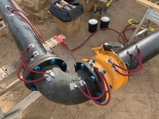
Continuity Straps across Flanges for providing Cathodic Protection.
The question in this issue looks at the role of an inspector.
Question: What makes a good coating inspector? CM
Answer: This is an interesting question and has numerous answers in my opinion. Having worked in industry for some 40 odd years, and been on all sides of the fence including sitting on it, I feel I am able to give the following judgements. The first and foremost criterion to be met is that an inspector needs to be completely independent and must not have their judgement swayed by allegiances or obligations. Until the advent of the ISO 9001, inspectors were employed by clients to provide objective and impartial viewpoints from an unbiased stand point, providing accurate and valid reports on the performance of a contractor’s work. They were generally put on site to act as a ‘Jiminy Cricket’ to witness, observe, and report back, as to what was going on, this, if done well would ensure that the contractor would be less likely to cut corners and use improper practices.
Up until 1987, BS5750 had been the governing system in the UK for business management but the arrival of ISO 9001 saw this coming to an end and the introduction of self-certification for contractors, this effectively destroyed the impartial third party inspection in the UK with an overnight hammer blow. Inspection in an instant became the domain of the contractor and many unscrupulous contractors immediately saw this as a license to print money as the poacher became both poacher and gamekeeper overnight. This led to the demise of many of the highly reputable inspection companies over the next few years.
It wasn’t until several years later when the clients started to actually look at, and audit, the works being undertaken under the ISO 9001 banner did they start to realise that things were not all that they seemed. From this a drive started to push forwards to try to put in place mitigation to prevent this from happening again.
The other major stumbling block that has often prevailed is the attitude of individuals who see inspection as unnecessary and a cost best avoided, how often do we hear the fateful words ’how difficult is it to paint a bit of steel? My wife manages to paint the house so it can’t be difficult at all!’ WRONG! Our business is highly technical and calling it painting is a huge mistake, paint is cosmetic and decorative! What we are involved in is the application of high-performance protective coatings and so we need people with a high level of technical knowledge to administer, as well as a well-trained and understanding workforce.
A properly constructed specification and contract is now seen as the best way forward to ensure contractor inspection is fit for purpose and that the personnel are properly trained and certified via a recognised body as competent.
From this we need to look at what the inspector’s role should be today, and what makes a good inspector. Inspection needs to be stand alone, you cannot blast or coat a piece of steel then inspect it and certify it yourself, as unfortunately still so often happens.
Many coating inspectors have worked their way up through the ranks and prove to be highly suitable and capable to undertake the coal face inspections. With the aid of quality training and access to all the right equipment, these people provide a solid and reliable backbone to the industry. What they do need is a proper and competent system of support, both from more highly qualified and experienced inspectors controlling and monitoring them, and with a management team that appreciates the true ramifications and the importance of inspection.
A good basic inspector should therefore be someone who is truly enthusiastic about his role and understands that he must at all times be an observer and not try to run the job, his role is the duty to collect and collate information, and report back to line management with his findings, and not get involved in front line confrontation. That does not mean to say that he cannot be authorised to discuss what he finds with the foreman or other management on the project but telling a worker what to do by bypassing the chain of command generally ends up badly. A basic inspector is not a basic person, he needs to have a large amount of experience and understanding of how the jobs are undertaken and the limitations of what is trying to be achieved. A good technical grounding is essential as well as the ability to communicate clearly, concisely, and correctly. One of the absolute essentials is training by a recognised training body with certification stating that the inspector has been trained and assessed to a given level and what they are competent to undertake and what level of supervision they require. For example the ICorr Coating Inspector training courses delivered by Argyll Ruane.
The knowledge required as an inspector moves further up the hierarchy, and becomes more varied and more technical. Ideally when the levels of dealing with contracts, documentation, auditing and failure analysis are reached, very comprehensive inspection training is needed as well as other technical qualifications such as degrees in chemistry, organic chemistry, metallurgy and materials, or process engineering. This gives the necessary level of understanding and authority to state the case when decisions need to be made and if necessary enforced. An inspector’s life is not a simple one, and having an open mind, unbiased view point, an inquisitive nature, a strong, unwavering sense of right and wrong, a good sound training background along with something resembling a sense of humour and the hide of a rhinoceros, all go a long way to making a good inspector.
Question:
When should you use corrosion resistant alloys in upstream production? CM Answer:
This is a wonderfully simple question that does not have a simple answer. Corrosion Resistant Alloys can be an excellent material choice for combatting corrosion and they are an important addition to the options that we have as Materials and Corrosion (M&C) professionals. However, as with all materials there are pros and cons and it is the role of M&C engineers to evaluate the best option.
It is important that we recognise that when we talk about a Corrosion Resistant Alloy (CRA) we are referring to a specific metal or alloy that is resistant to a specific corrosion mechanism or mechanisms. For example, in Upstream operations, for some applications,316L stainless steel is increasingly used for its resistance to carbon dioxide (CO2) corrosion, and can be considered a CRA for this threat. However, this alloy is vulnerable to corrosion in oxygenated sea water and so is not a good material for this environment. So before selecting a corrosion resistant material, in additional to many other parameters, it is very important we define the corrosion mechanism or mechanisms that it needs to resist – on both the internal and external surfaces of the equipment.As in the example above many CRA’s are stainless steels, and historically the term “stainless steel” was used generically to indicate corrosion resistant metals. The term CRA emerged when alloys that do not have iron (Fe) as their majority element started to be used, e.g. nickel and titanium based alloys.
For our colleagues who are not M&C engineers, the term CRA can be misleading because there is no metal or alloy that is immune to every corrosion environment. To make this point I have sometimes joked that CRA should mean “Can Rust Actually”. A key role of M&C engineers is to educate colleagues on the limits of CRA’s in particular environments.
A further consideration when selecting a CRA is that we do not eliminate one corrosion mechanism only for it to be replaced by another. For example many stainless steels are resistant to CO2 corrosion but vulnerable to cracking mechanisms (e.g. Chloride Stress Corrosion Cracking (SCC), Sulphide Stress Cracking (SSC)). In some cases it may be preferable to have a corrosion mechanism where the metal loss can be safely monitored with inspection versus a cracking mechanism which can occur suddenly and without any warning.
Other considerations when considering CRA’s are:
1.
Cost: CRA’s are more expensive than carbon steels and so this needs to be factored into the economics of a project. This is known as “whole life costing” and includes procurement, construction, operation, and decommissioning costs. Typically, CRA’s become more attractive as the required lifetime of a project increases.
2.
Welding: CRA’s require extra care when welding compared to carbon steels which adds to the cost of construction. It also requires welders who are more highly qualified and so another consideration is, will these welders and quality control personnel be available locally at the project site. This is often related to where in the world the project is located.
3.
Galvanic Corrosion: Since CRA’s are more resistant to corrosion than carbon steel, problems can occur when they are joined to carbon steel or other more corrosive materials. The CRA can act as a cathode which promotes corrosion of the other metal. Incorrectly specified weld material is especially vulnerable to this, resulting in Preferential Weld Corrosion.
4.
Construction & Commissioning: If a CRA is selected to resist a specific operational corrosion threat, such as CO2 corrosion, it is important to ensure that during the construction and commissioning phase it does not come into contact with a fluid that is corrosive to it. There are many examples where this has occurred. Probably the most well-known examples are where a stainless steel has been chosen for a pipeline for its CO2 resistance but during commissioning it has been hydrotested with poor quality water which contains chlorides and oxygen (and often bacteria) causing the stainless steel to corrode and/or crack before it ever enters operational service.
5.
Availability: Due to manufacturing challenges and mill constraints, CRAs may not be readily available, and often have a long lead time.
Having considered all these factors let’s now return to the original question of when to use CRA’s in upstream production. Before considering CRA’s, it is usual to evaluate carbon steel as a base case for construction. Once this has been done CRA’s can be evaluated and compared to the carbon steel base case. Key considerations on top of design factors including mechanical properties, are:
1.
Risk: CRA’s are often selected when the risk of premature failure of equipment made from carbon steel is unacceptable. If a project is expected to last 25 years but the mitigated corrosion rate of carbon steel will render the equipment unusable before that, then a CRA is likely to be a good option. Some engineers would like to be able to use a maximum, uninhibited corrosion rate for carbon steel as the trigger for moving to CRA’s, e.g. 3 mm/y. Whilst this provides a simple approach it is not the corrosion rate that is key – it is the time to failure that is important. Note that failure is not the point at which the equipment perforates and leaks ( often known as a loss of primary containment – LOPC), but the point at which it no longer meets the pressure requirements of the equipment. There are well known operations that have uninhibited corrosion rates of >5mm/y that are constructed from carbon steel in which corrosion is successfully mitigated to 0.1 mm/y
or lower.
2.
Operability: This is related to the risk section above but is worth noting separately. In many cases upstream equipment can be constructed from carbon steel and both internal and external corrosion successfully controlled using a combination of chemical inhibition, coatings, and/or cathodic protection. However, these mitigation systems are known as “active” mitigation and require monitoring, maintenance and repairs to be undertaken during the life of the operation. These require appropriately qualified personnel which incur operational costs. Moreover in remote land-based locations the facilities can be spread over very large areas, requiring staff and equipment to be driven for many hours – often called “windshield time” which is unproductive time and has associated safety risks. In such cases it may be more appropriate to select a CRA which would significantly reduce many of these activities and reduce the total risk of an operation. Similar arguments apply to subsea operations which are difficult and costly to access. Today, many subsea facilities are built entirely out of CRA’s for this reason.
3.
Cost: This was discussed previously and is a key factor in deciding between carbon steel and CRA materials. The M&C engineer will need to look at the whole life costing of both options, which will then be assessed by the project commercial team, who will make a decision based on all project risks
and costs.
In summary, hopefully it is clear that there are many factors to consider when selecting a CRA for upstream equipment. Sometimes the decision to use a CRA can be simple and examples of this include:
1. When corrosion rates of carbon steel are unacceptably high.
2. When the construction and operational costs for managing a carbon steel facility exceed the cost of using CRA for the project.
3. When the risk of maintaining an active mitigation system for carbon steel equipment is unacceptable.
4. And finally, when a combination of very high strength and corrosion resistance are essential.
However, it is far more common that the decision is not simple and it is the role of the M&C engineer to consider the risks and costs of both carbon steel and CRA options for a project. It is also usual that a single engineer will not have all the skills necessary to make this decision and will call on colleagues with specialised knowledge of materials and corrosion to support the evaluation.
Further Reading
There are many excellent sources for further information on CRA’s – some good starting points are:
1.
https://nickelinstitute.org/media/1663corrosionresistantalloysintheoilandgasindustr
2.
Bijan Kermani, Fellows Corner, Corrosion Management, Issue 165, Institute of Corrosion Magazine, January/February 2022, page 19.
3.
B. Kermani and D. Harrop, “Corrosion and Materials in Hydrocarbon Production”, published by John Wiley & Sons td, 2019. (note this book is an excellent reference and covers all aspects of upstream corrosion and materials topics).
Bill Hedges, Past President ICorr
The questions in this issue feature insulated stainless steel pipework, and transporting CO2
Question:
Should 304 stainless steel pipework be coated prior to insulation? CM
Answer:
Corrosion under insulation in austenitic stainless steel manifests itself in the form of chloride-induced stress corrosion cracking (CISCC), also referred to as external stress corrosion cracking (ESCC), as the source of chlorides is external to the process environment.
The mechanism of stress corrosion cracking (SCC) is well known in industry and can be found in lots of publications which are in the public domain. The mode of cracking failure is typically trans granular. There are a number of conditions that are in play when it comes SCC, as detailed below:
1. A susceptible 300 series austenitic stainless steel, in this case 304
2. Residual or applied surface tensile stresses
3. The presence of halides from either the environment of the insulation itself
4. Process temperatures leading to metal temperature in the range 50° to 150°C
5. An electrolyte (water)
All of the above are ever present, and hence the need to use specific coatings on stainless steel. The types of coating that can be employed are varied depending on the operating temperature, typically:
• Organic epoxy chemistry is capable of resisting cryogenic temperatures and up to 120/150C, depending on formula
• Epoxy phenolics/novolacs are suitable from cryogenic temperatures and up to 200/230C, again depending upon formula
• Inorganic coatings such as Inert Multipolymer Matrix, are also capable from cryogenic temperatures and up to 600C
These coatings when formulated correctly, using barrier pigmentation such as Micaeous Iron Oxide (MIO), aluminium flake or glassflake, will create a barrier to the ingress of chlorides to the stainless steel substrate.
There is also the matter of the insulation to consider when it is being used. It is well documented that with traditional insulation, and mineral based insulation with a metal jacket, that water will penetrate into the insulation system. The water will find a way through breakages in the metallic jacket or joints edges, and then it will soak through the insulation giving rise to CUI/CISCC conditions. Under certain operating conditions up to 177C, the traditional insulation could be replaced with a thermal insulation coating system (TIC) especially in the case where personal protection is required. This will remove the conditions which are required for CUI, and reduce the risk on CISCC, as no electrolyte is being held at the surface.
Therefore, a combination of a good barrier coating with high temperature resistance and a thermal insulation coating could be a very good choice in combatting both CUI and CISCC.
Neil Wilds, Global Product Director –
CUI/Testing, Sherwin-Williams, Protective & Marine Coatings.
Question:
Carbon capture and pipelines/storage – what are the limits of impurities when transporting CO2? PF
Answer:
Like many ‘Ask the Expert’ questions, there is no simple answer to this! Although general industry guidance on impurity limits is available from a number of sources [1-4], there are no internationally agreed specifications for CO2 composition during pipeline transport. Under current regulations, the responsibility lies with the pipeline operator to carry out their own assessment and specify impurity limits during the design phase of a given CO2 pipeline project. These limits can vary significantly depending on the composition of the CO2 stream, the economics of the purification technologies used and the operating conditions of the pipeline.
From a corrosion perspective, the most important impurity to consider is obviously water. When the water concentration is below its solubility limit in dense phase CO2 (~ 2500 ppm under typical pipeline operating conditions in the absence of other impurities) no corrosion will occur. However, the presence of other impurities can increase the likelihood of corrosive phases forming, either by reducing the water solubility or via chemical reactions between different impurities. Acid dropout is the most significant concern for pipeline operators, whereby highly corrosive aqueous phases, such as nitric and sulphuric acid, can form as a result of reactions between water, NOx, SOx, O2 and H2S impurities.
Assessment of the risk of water and acid dropout in CO2 pipelines due to the presence of multiple impurities is a complex process, which requires an understanding of the thermodynamics of fluid composition, the impact of operating temperature and pressure variations (including potential upset conditions) and interactions between impurities. The requirements for ship transport are typically more stringent than those for pipelines [5], with lowest temperatures representing the worst-case scenario.
Published corrosion rate data in the open literature should be treated with caution due to challenges in control of test parameters and the high degree of uncertainty around the correlation between laboratory test data and real world application. Combined with the relative lack of service experience in transport of CO2 captured from a range of industrial sources, this often leads to a degree of over-conservatism in materials selection. For CO2 specifications, thresholds in relation to acid drop out are set based on limited available data (often not lower than 25oC) and are therefore likely not conservative enough. The development of reliable standard test methods that are more representative of service conditions will go a long way towards addressing these issues.
A full description of the process for developing reliable CO2 impurity specifications for individual projects is clearly beyond the scope of this response but the interested reader is directed to the references below as a starting point.
References
1. DNV-RP-F104 – Design and operation of carbon dioxide pipelines, Recommended Practice, September 2021
2. Briefing on carbon dioxide specifications for transport, EU CCUS PROJECTS NETWORK, November 2019
3. DYNAMIS CO2 quality recommendations, EU DYNAMIS project D 3.1.3 report, June 2007
4. Materials challenges with CO2 transport and injection for carbon capture and storage, J. Sonke, W.M. Bos, S.J. Paterson, International Journal of Greenhouse Gas Control 114, 103601, 2022
5. Network Technology Guidance for CO2 transport by ship, ZEP/CCSA Report, March 2022
Gareth Hinds, NPL
The question in this issue features the type of coating needed for the internal protection of an above ground storage tank.
Question:
What type of generic coating is required to protect the inside of a tank containing a liquid with pH ranging from 2-13, and operating at between 65-80 C? PS PS
Answer:
The range of possible conditions covered make this a fairly difficult question to answer. When responding to queries where all the information required has not been provided, the specifier will need to err on the side of caution and generally ends up in the proposal being over specified in an attempt to cover the unknowns, in this case, in the tank. Over-specified linings generally increase cost and complicate application requirements. It is also the case that the more expensive a system is, does not necessarily make it a more suitable solution, as every lining has its own strengths and weaknesses.
The first question should always be what is the existing coating solution? If this is maintenance, what was previously used and was it successful? If it failed, do we know how and why?
Details of the chemicals involved, and their concentrations are required before a specification can be given, including durations in the different states (acidic and alkaline). Is the temperature a genuine continuous service temperature or are there short-term spikes to these maximums, or is the higher a design temperature (if achieved the lining is the least of the operator’s worries) and the lower the actual service temperature? What is the tank substrate, steel or concrete? All these will affect the lining selection.
With the wide range of pH quoted, this could be a neutralisation tank or pit and this type of aggressive service conditions often require a high build reinforced vinyl ester system. These systems are made up of a number of layers, including a trowel applied screed and glass fibre reinforcement mat to create a robust chemical resistant system, but the system cannot be confirmed until full details are known.
We use cookies to optimize our website and our service.
Functional
Always active
The technical storage or access is strictly necessary for the legitimate purpose of enabling the use of a specific service explicitly requested by the subscriber or user, or for the sole purpose of carrying out the transmission of a communication over an electronic communications network.
Preferences
The technical storage or access is necessary for the legitimate purpose of storing preferences that are not requested by the subscriber or user.
Statistics
The technical storage or access that is used exclusively for statistical purposes.The technical storage or access that is used exclusively for anonymous statistical purposes. Without a subpoena, voluntary compliance on the part of your Internet Service Provider, or additional records from a third party, information stored or retrieved for this purpose alone cannot usually be used to identify you.
Marketing
The technical storage or access is required to create user profiles to send advertising, or to track the user on a website or across several websites for similar marketing purposes.