
How do we Detect and Mitigate AC Interference in Pipelines Using Software Modelling?
J N Agrawal, B Tech, MBA, ICorr CP4, FICorr, CEO of Corrsol Tech, India
Meet the Author
Jaiprakash Narain Agrawal is an expert in corrosion management and cathodic protection. He has a wide experience in pipeline integrity management and cathodic protection for 40 years. Jaiprakash has worked in projects, construction, operation and maintenance of oil and gas pipelines. Jaiprakash has presented papers in corrosion related subjects at AMPP and ASME conferences in India. He has also authored books on cathodic protection and pipeline integrity management. Jaiprakash also initiated a process for corrosion audits for gas pipelines. He has contributed to the preparation and implementation of procedures for various CP monitoring techniques. Jaiprakash received the AMPP India corrosion awareness award in 2023 for his contribution in corrosion science and technology in industry.
For the last 7 years he has been a certified ICorr Level 4 CP specialist. He is an independent consultant and CEO of Corrsol Tech and engaged in providing solutions in corrosion control, pipeline integrity management and cathodic protection. Jaiprakash has carried out pipeline integrity assessments including fitness for purpose (FFP) and remaining life assessment (RLA) of onshore and offshore pipelines. He has also been involved in conducting training and coaching in pipeline integrity management (PIM) and cathodic protection (CP).
He has published more than 30 technical papers in peer-reviewed events and journals and has provided industry training on integrity management and CO2 and H2.
Background
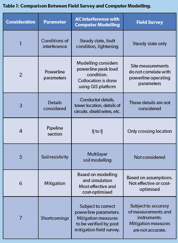
Electrical interference by alternating currents (AC) is a major consideration for oil and gas pipelines. Computer modelling can be used to assist with its mitigation. AC interference corrosion in pipelines typically occurs when alternating current (AC) from nearby power lines induces a voltage on the pipeline, leading to corrosion, especially at small coating defects. This phenomenon is a serious concern due to the potential for rapid and localised damage, even in pipelines with cathodic protection.
What is Software Modeling?
Computer modelling is based on the simulation of all field data and the assessment of AC interference based on computer modelling with the following outcomes:
• The results are usually more accurate than field surveys alone, as data simulation is assisted by computer modelling.
• Various mitigation strategies can be implemented based on computer modelling outcomes for the most effective and cost-‘optimised’ manner.
• The most important features required for effective mitigation are:
Configuration of grounding
Location of grounding
Selection of materials of grounding
Effectiveness can be checked after implementation of mitigation measures.
Background
Electrical interference by alternating currents (AC) is a major consideration for oil and gas pipelines. Computer modelling can be used to assist with its mitigation. AC interference corrosion in pipelines typically occurs when alternating current (AC) from nearby power lines induces a voltage on the pipeline, leading to corrosion, especially at small coating defects. This phenomenon is a serious concern due to the potential for rapid and localised damage, even in pipelines with cathodic protection.
What is Software Modeling?
Computer modelling is based on the simulation of all field data and the assessment of AC interference based on computer modelling with the following outcomes:
The results are usually more accurate than field surveys alone, as data simulation is assisted by computer modelling.
Various mitigation strategies can be implemented based on computer modelling outcomes for the most effective and cost-‘optimised’ manner.
The most important features required for effective mitigation are:
Configuration of grounding
Location of grounding
Selection of materials of grounding
Effectiveness can be checked after implementation of mitigation measures.
Impact of Contradiction Between Field Survey and Simulation Result
•Designed mitigation measures may be ‘more or less’ compared to actual or required.In case of more than required, cost will be more.
• In case of less than actual required, effectiveness will be less.
•Pipeline will be affected in case of ineffective mitigation measures. however, simulation results can be verified by the field survey results.
•Even then, errors may happen in case of inaccurate data or interpretation of the simulation results.
Possible Reasons for Contradiction in Software Simulation Results and Field Data
• Global earthing systems.
• Local earthing systems.
•Parallel underground pipelines in the vicinity of the powerline or electric traction.
• Inadequate pipeline coating parameters.
• Influence of soil resistivity in the field and simulation software.
• Actual or real-time load current instead of maximum load current
of powerline.
Computation of Induced AC Potential and AC Current Density Based on Real Time Load Current or Peak Load:
• Field survey is performed for AC induced voltage and AC current density based on real time load current while simulation is done based on peak load current.
• Hence, AC induced voltage and AC current density will vary. Simulation results are on the higher side than field surveys.
• The mitigation measures based on simulation results consider optimum conditions.
• Powerlines generally run on load, which is less than the peak load but may reach peak’ load at peak hours.
• Powerlines are designed to withstand higher load capacity.
• Actual load current data consideration will give almost similar results as simulation software provides.
Possible Solutions to Achieve More Accurate Results
• Accurate multi-layer soil resistivity data is required for software simulation.
• Reliable and accurate software with high calculation accuracy is preferred.
• Software should allow multiple input parameters and provide precise simulation results.
• The accurate and calibrated instruments should be used with recommended technique by a certified and experienced CP technician.
• Real time load data should be used instead of peak load.
•n Simulations must consider other factors such as global earthing system (GES), local earthing system (LES), pipeline coating characteristics and parallel pipelines.
• Simulation results should invariably match with field survey.
Case Study of AC Interference and Mitigation with Computer Modelling Using the Following Input Considerations
• Material of Construction: carbon steel
• Outside Diameter (OD): 10”
• Length of pipeline: 112 Km
• Wall Thickness: 6.4 mm
• Coating: 3LPE
• Coating Leakage Resistance: 60000 Ohm-m2
• Minimum Coating Thickness: 3mm
• Pipeline Burial Depth: 1.5 meters from Finished Ground Level (FGL)
• Existing grounding locations: 32 Nos
• SV/IP stations earthing locations: 10 Nos
• Grounding material: Copper conductor/Zn anodes 10 Kg
• Number of transmission lines running parallel/crossing pipelines: 14
• KV rating of transmission lines: 132, 220, 400
• Normal load/peak load in A: 15 to 260/25 to 589
• Simulation done from peak load.
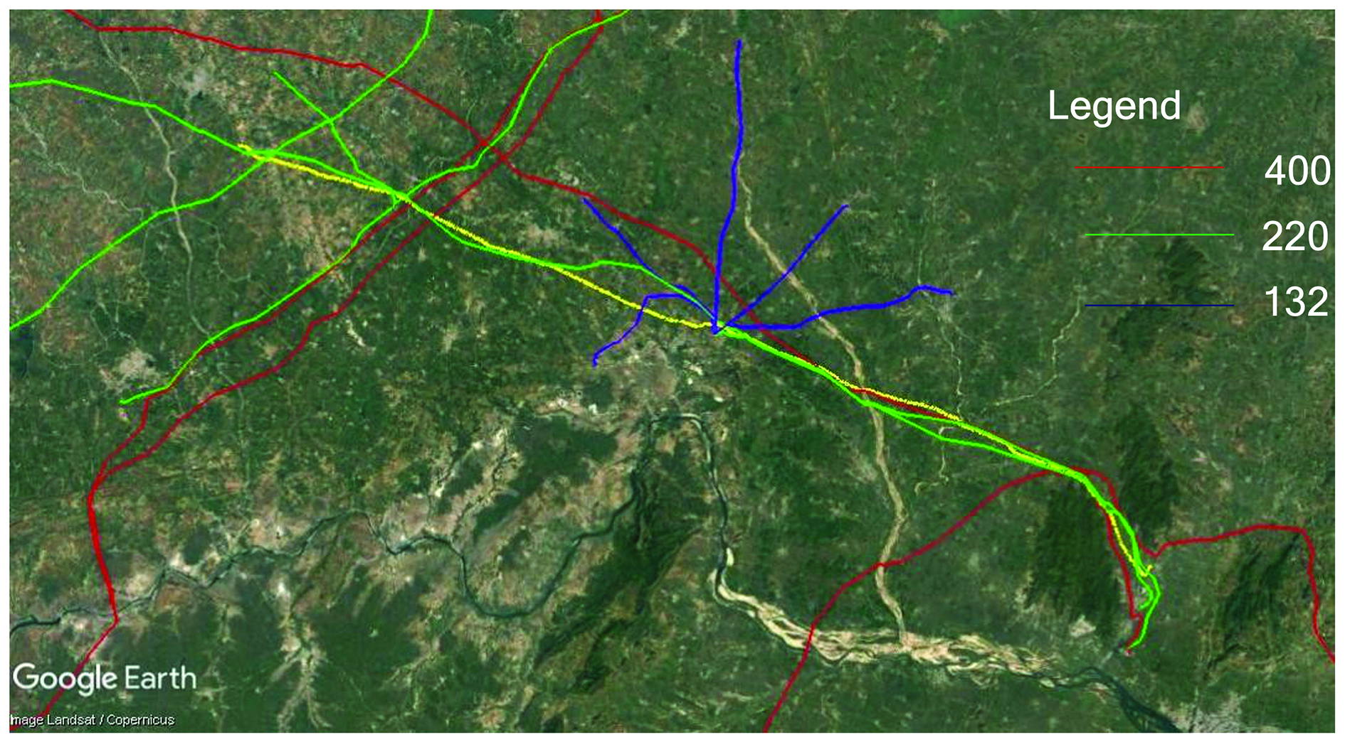
Figure 1: Interpolation of Transmission Line and Pipeline.
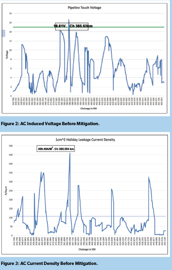
Interpretation of Results with Existing Pipeline Ground Points
Key Observations
•Induced AC voltage in the pipeline is proportional to the load current in the transmission line as load current varies at different lines.
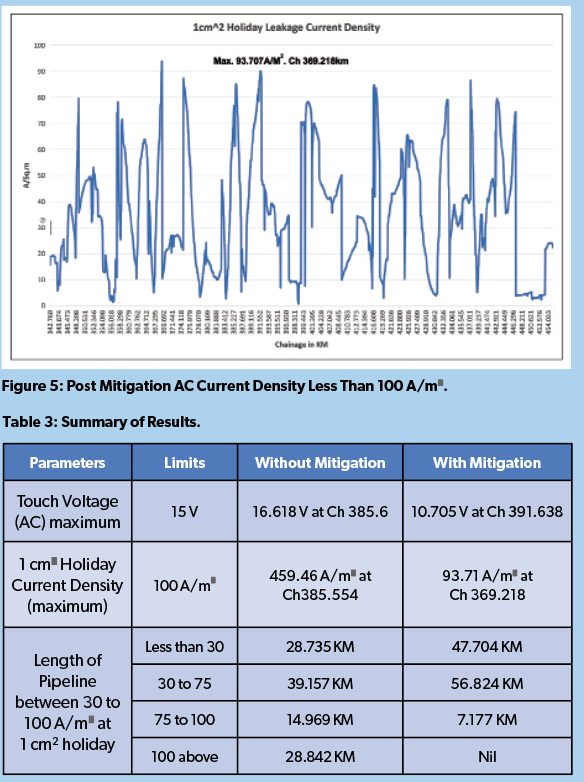
•The touch voltage on pipeline exceeds the prescribed safe limit of 15V with a maximum of 16.618 V at chainage 385.63 KM.
•High values of current density between Chainage 382.8 and 386.43 km where induced AC voltages are higher and soil resistivity is low.
•The current density exceeds the prescribed value of 100 A/m2 for about 28.84 KM as shown in the figure.
•Induced AC voltage and AC current density can be interpolated to draw the conclusion that wherever AC current density is higher, AC induced voltage is also higher but higher induced AC potential may not cause higher AC current density if soil resistivity is higher.
•An interpolated graph of pipeline route with chainages and transmission line along with a graph showing chainages, soil resistivity, induced AC voltage and AC current density will establish relationship with multiple parameters.
Material Specification for Grounding Depending Upon AC Current Density and Length of Parallelism
A copper conductor wire of following specifications is required
• AWG No 6.
• Overall Diameter: 38 mm.
• Length: 25.4 m, 76.2 m and 152.4 m in horizontal configuration.
•To be placed at 1m from pipeline wall and at the same depth as of pipeline.
•Copper conductor shall be connected to pipeline through DC Decoupler.
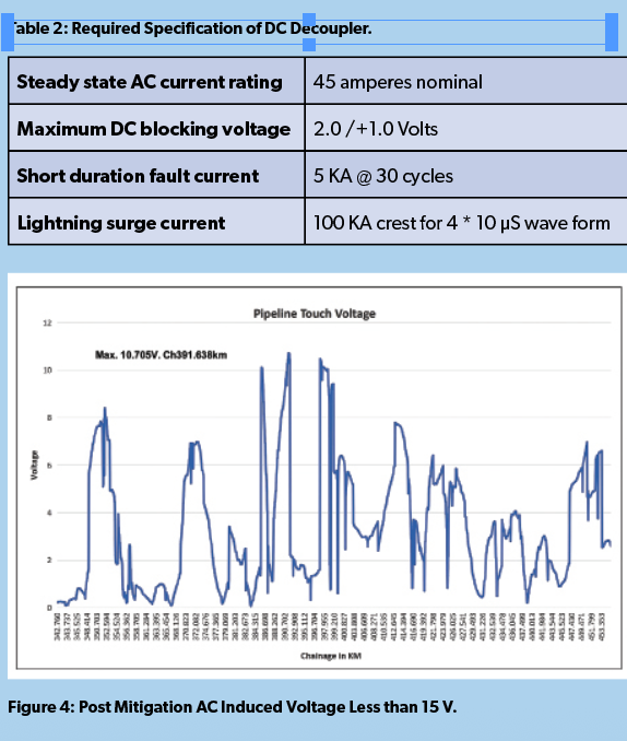
Case Study Conclusion
The major observation is this case study was that existing grounding/earthing arrangements were not adequate to ground induced AC potential and limit AC current density because of wrong location or wrong grounding material. Further work would be required for this and other similar situations.
References
1.NACE SP 0177–2014: Mitigation of Alternating Current and Lightning Effects on Metallic Structures and Corrosion Control Systems.
2.NACE SP 21424:2018: Alternating Current Corrosion on Cathodically Protected Pipelines: Risk Assessment, Mitigation,
and Monitoring.
3.EN 50443:2012 Effects of Electromagnetic Interference on Pipelines Caused by High Voltage.
4.BS EN 15280 – 2013 – Evaluation of AC. corrosion likelihood of buried pipelines applicable to cathodically protected pipelines.
5.Criteria for Pipelines Co-Existing with Electric Power Lines, prepared for The INGAA Foundation by DNV GL.
6.CEPA – A/C Interference Guideline Final Report – June 2014 and INGAA or CEPA for mitigation measures.
7.ISO 15589 Part I – Cathodic protection of pipeline/structure transportation systems – Part I-On land pipeline/structure, issued by the International Organisation for Standardization (ISO).