AkzoNobel has extended its Chinese marine coatings partnership to accelerate transition to sustainable shipping.
A strategic agreement has been signed between AkzoNobel’s Marine Coatings business and Winning Shipping in China which will help accelerate the maritime industry’s transition to lower carbon operations.
The two companies have been partners since 2016 and the expanded collaboration will involve AkzoNobel supplying a significant volume of International® coatings for a number of drydocking projects in 2026. Focused on six vessels, it will enhance the fleet’s operational efficiency and environmental performance. At the core of the latest agreement is Intersleek® 1100SR product – the world’s first biocide-free fouling control coating to feature patented “slime release” technology. It delivers outstanding fouling control and significantly reduces hull resistance, helping fleets to save fuel and cut greenhouse gas emissions.
“The outstanding performance of International has been fully validated in our existing fleet, delivering significant fuel savings and enhancing our market competitiveness,” says Yu Shan, General Manager of Qingdao Winning International Ship Management Co., Ltd. This is why we’ve chosen to extend and deepen our partnership. Through this drydocking cooperation, we look forward to more vessels benefiting from these more sustainable advanced technologies, jointly contributing to a greener future for the industry.”
Photo: The Winning Youth bulk carrier is coated with products supplied by AkzoNobel
Following the International Maritime Organization’s introduction of emission reduction regulations, shipping companies are addressing their carbon footprint and actively adopting measures to optimize energy efficiency. China is also speeding up the implementation of its “Dual Carbon” strategy in the maritime sector, promoting the widespread adoption of more sustainable technologies. “We’re honoured to continue and deepen our strategic cooperation,” said Rob Leslie, Commercial Director of AkzoNobel Marine and Protective Coatings in Greater China. “Winning Shipping’s unwavering pursuit of more efficient operations aligns perfectly with our philosophy of helping customers through sustainable innovation. We look forward to providing solid support for the long-term operational efficiency and sustainable development goals of its fleet.”
In addition to Intersleek 1100SR, International will also supply the project with its Intercept® 8500 LPP antifouling coating, which combines linear polishing with an optimized biocide package. This is the highest performing antifouling product within the International range, specifically designed for deep sea vessels.
This agreement was signed during the recent Marintec China 2025 event, one of the world’s leading maritime industry exhibitions.
Hempel A/S has launched the latest addition to the Hempaline Defend family; Hempaline Defend 430, a next-generation tank lining created to help energy operators boost efficiency, minimise downtime and extend maintenance intervals. The solvent-free, epoxy phenolic lining streamlines application, lowers energy use during installation and supports more sustainable operations by reducing VOC emissions and workplace hazards. By combining single-coat efficiency with rapid curing and long-term durability, Hempaline Defend 430 enables asset owners to keep tanks in service longer while lowering lifecycle costs.
Hempaline Defend is a range of high-performance lining solutions engineered for the demanding conditions of the energy and process industries. Designed to withstand corrosion, high temperatures, abrasion and exposure to a wide spectrum of chemicals and solvents, these linings provide reliable long-term protection. By reducing maintenance needs and extending service life, Hempaline Defend helps operators maximise uptime and lower total lifecycle costs. “After a trial application with a major tank builder, customer feedback was that the shorter inspection time, compared to their existing lining, would significantly improve output in their workshop,” Matthew Fletcher, Segment Development Manager, Linings at Hempel A/S commented that: “With Hempaline Defend 430, asset owners benefit from a solvent-free lining that can be applied in a single coat, returned to service quickly and approved even for the most sensitive cargos and with a temperature resistance up to 90°C and strong hydrocarbon resistance, Defend 430 truly offers a versatile one-product solution for storage tanks.”
Key technical highlights: • Solvent-free epoxy phenolic lining for energy storage tanks • Single-coat application at 400 µm (16 mil’s) • Rapid return to service: 3 days at 20°C • Withstands crude oil up to 93°C (200°F) • Approved for potable water (WRAS) and jet fuel (EI1541) • Inspection interval extension up to 5 years (API 652 & 653 compliant with optional glass fibre mat reinforcement) • Compatible with Hempaline Prepare 130 primer for immersion up to 90°C
You can learn more about Hempaline Defend right here.
Oceaneering
Oceaneering Wins ASQE Diamond Award for Quality Excellence
Photo: The ASQE Diamond Award
Houston, Texas – Oceaneering International, Inc. has been honoured with the American Society for Quality and Excellence (ASQE) Diamond Award, one of the most prestigious recognitions in the quality industry. Oceaneering was one of only two companies selected for this award in 2025, reflecting a commitment to performance excellence and innovation.
The Diamond Award is presented to organizations that achieve the highest maturity scores in the annual Insights on Excellence® (IoE) Benchmarking Tool survey. This recognition signifies exceptional standards of quality and continuous improvement, recognizing organizations that integrate best practices into every aspect of their operations.
Oceaneering’s 2025 results demonstrate a progressive Quality culture, as defined in the IoE maturity model, and predictable and consistent delivery of services and products that meet or exceed customer expectations. Winners were recognized during the Excellence Roundtable event in November, coinciding with World Quality Month.
Julie Sitzmann, Director, Quality Solutions, at Oceaneering, said: “Oceaneering is committed to performance excellence, and this recognition reflects that our quality management system and culture are delivering as intended. We are proud to be one of only two companies honoured with the Diamond Award, which highlights our commitment to quality and consistent execution across the organization.”
Learn more about Oceaneering’s approach to Quality.
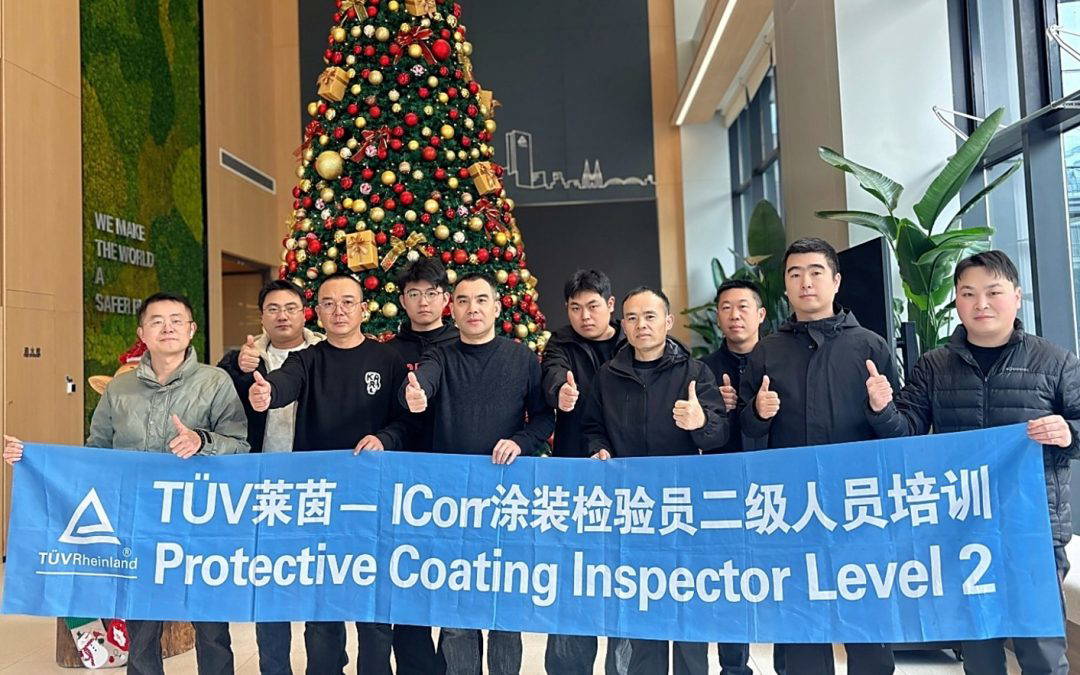
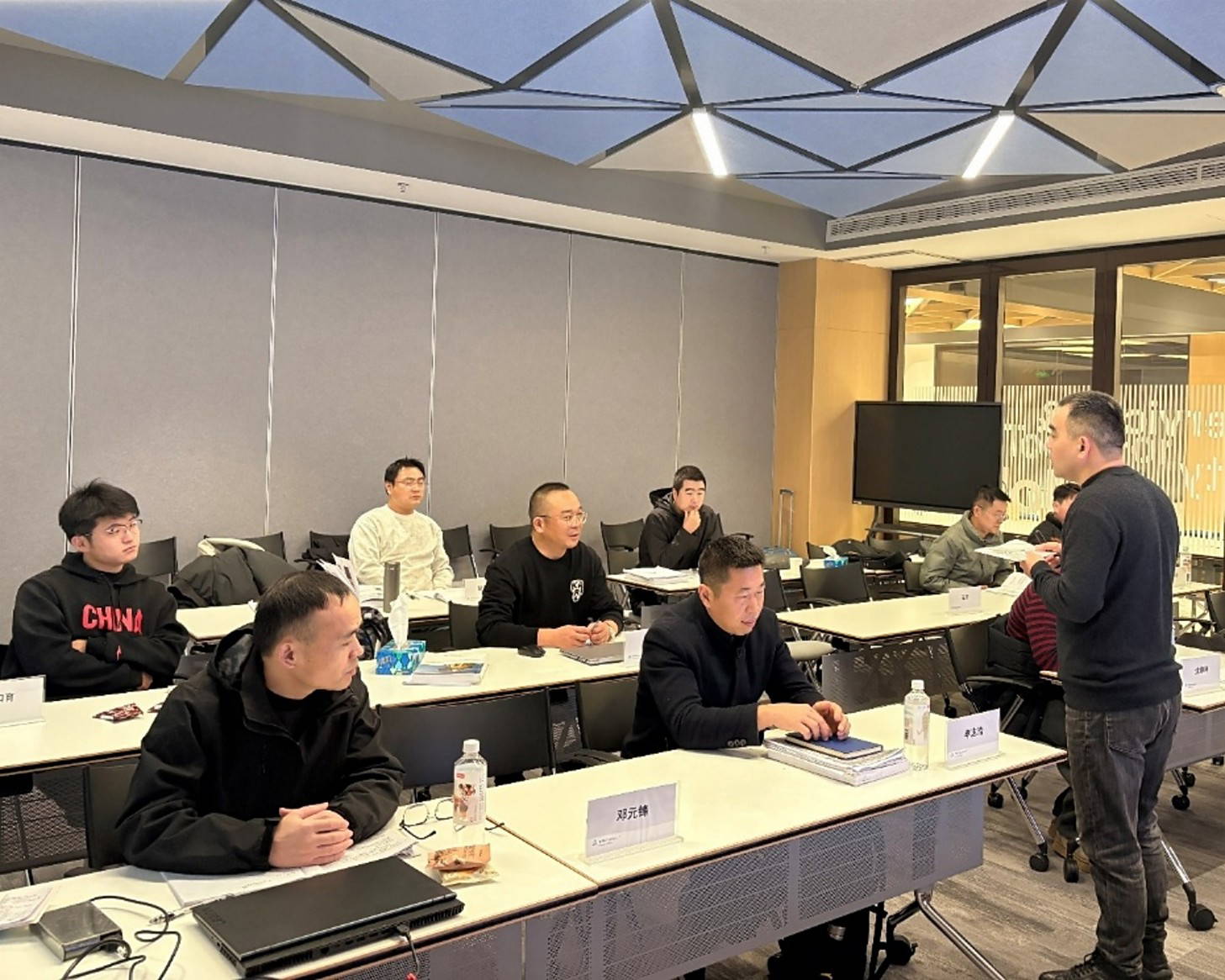
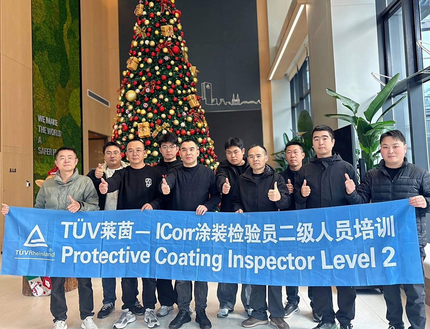
TÜV Rheinland, (Technischer Überwachungsverein) are a very well-established ICorr/ARL (Argyll Ruane Ltd) Training partner.
They have issued 133x ICorr Training Certifications and 68x ICorr Training Re-Certifications in 2025 alone, from their Shanghai Training Centre.
Jing Anita Fang is the Key Account Manager for TUV Rheinland in China.
Photo: TUV HQ, Shanghai
About TÜV Rheinland
TÜV Rheinland, founded in 1872, is a global leader in technical services, providing safe and sustainable solutions for the interaction between humans, the environment, and technology. Since 1996, they have offered training and personnel certification in China, being Europe’s largest independent education institute. TÜV Rheinland Industrial Services Greater China, comprising world-leading experts, delivers technical inspection, testing, and certification for the oil, gas, chemical, petrochemical, energy, power, construction, and process industries worldwide. Their comprehensive services ensure products and equipment meet market requirements, supporting local industries in developing safely and sustainably.
History with ICorr
In collaboration with Argyll Ruane, TÜV Rheinland has successfully introduced ICorr training to China, becoming the sole ICorr training provider in the country in 2018. On-site training is conducted in coastal cities such as Shanghai, Tianjin, Qingdao, Zhuhai, Qidong, and Zhoushan, where numerous international offshore FSPO and LNG projects are active. During 2024, ICorr, TÜV Rheinland (China) Ltd., and Argyll Ruane (Sheffield, UK) celebrated 7 years’ collaboration, and achieved the 1000th ICorr Certificate issue in China. In the same year, Protective Coating Inspector Training Level II and Level III have been delivered by TÜV Rheinland, where all ICorr surface treatment courses are available for the candidates in China now.
Ivano Magnifico, Certified Senior Technician in Cathodic Protection.
Meet the Author Ivano Magnifico holds a master’s degree in Electronic Engineering and serves as the Gas and Oil Product Manager at Automa, an ICorr Corporate Member.
A certified Cathodic Protection Specialist, he combines technical competence with deep knowledge of market analysis and industry standards. With over 15 years of experience in remote cathodic protection monitoring and a patent for an intelligent reference electrode, Ivano has made significant contributions to the field. He is a member of the Board of Directors of CEOCOR (European Committee for the Study of Corrosion and Protection of Piping Systems) and serves as the Delegate of the AMPP Italy Ivano Magnifico Chapter. In addition, he is an active participant in ISO and AMPP standard working groups on cathodic protection.
Introduction
The risk of AC corrosion has always been linked to the parallelisms of underground pipelines with High Voltage AC lines, especially in those geographical areas where the morphology of the territory creates obligatory so-called “technological corridors” and therefore forces the coexistence of different services over long distances.
Recently, the greater diffusion of AC-powered railway networks has further increased the AC interfering sources, while the use of more performing coatings on underground pipelines has on the one hand increased their insulation from the surrounding soil, and on the other has increased the risk of overprotection compared to old, less performing, or more degraded coatings.
This paper, starting from a real case found in a gas distribution network, will present the normative criteria to be used to keep the AC corrosion risk under control, and will highlight how the simultaneous presence of cathodic overprotection may result in an autocatalytic cycle leading to accelerated AC corrosion, in which monitoring becomes essential in order to be able to carry out on time the appropriate corrective actions.
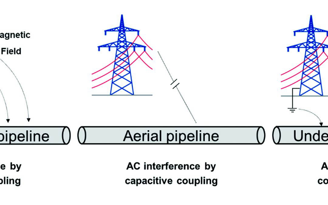
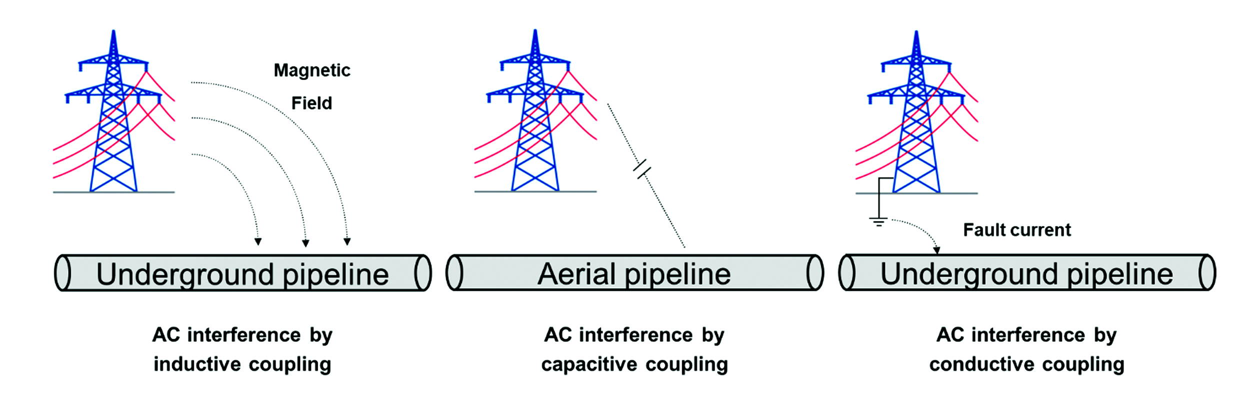
There are several mechanisms through which an AC source can interfere with a metal structure (Fig. 1): by inductive coupling, as an effect of the magnetic field generated with respect to an underground structure; by capacitive coupling, in the case of an aerial structure; and by conductive coupling in the presence of a fault current in the ground, in the case of an underground pipeline.
In the case of underground pipelines, under normal operating conditions, the mechanism that can generate AC interference is inductive coupling: normally the interference effect is greater as larger the length of the sections where the pipeline and the AC source (high voltage AC lines, railways operated in AC) follow a parallel path.
AC Corrosion Protection Criteria
International industry standards specify which electrical parameters shall be monitored and their maximum allowed values. The standard ISO 18086:2019 “Corrosion of metals and alloys – Determination of AC corrosion – Protection criteria” indicates two steps for the verification of permissible AC interference levels (Fig.2):
Figure 1: AC Interference Mechanism.
Figure 2: AC Corrosion Risk Assessment According To ISO 18086.
The first step relates to a safety criterion for maximum permissible touch voltage (15V threshold) and does not have a direct rule in AC corrosion risk assessment. This value considers a hand-to-hand or hand-to-foot resistance for an adult male human body of 1500 Ω, yielding a current flow of 10 mA when 15 V is applied [2].
The criterion is based on current density measurements carried out through a coupon whose surface is defined by the standard to be 1 cm², connected to the structure. Both AC current density and DC current density must be measured, as the level of cathodic protection can affect the AC corrosion phenomenon.
NACE standard SP21424-2018 “Alternating Current Corrosion on Cathodically Protected Pipelines: Risk Assessment, Mitigation, and Monitoring” [3] expresses similar values, where depending on the measured DC current density (J.dc) value, different levels of AC current density (J.ac) are allowed:
• If J.dc > 1 A/m2 then J.ac < 30 A/m2; or • If J.dc < 1 A/m2 then J.ac < 100 A/m2
This standard imposes a maximum AC current density limit even if the DC current density is less than 1 A/m², while the coupon surface of 1 cm² is indicated as generally used but not mandatory. The Spread Resistance is the ohmic resistance through a coating defect towards remote earth and controls the DC (Idc) or AC (Iac) current passing through a defect at a given voltage (Udc or Uac): Uac = R’s Iac or Uac = Rs J.ac (1)
where Rs is the normalized Spread Resistance expressed in Ω·m2.
On coating defects, where cathodic protection current reaches the steel surface, cathodic reactions occur involving oxygen reduction and hydrogen evolution. Both reactions generate hydroxide ions(OH-) leading to increased pH at the interface and alkalinity.
Since Spread Resistance depends [4] on both defect size (decreases as surface decreases) and pH value at the interface (decreases as pH increases), the DC current density reaching the defect affects it:
Lower current density leads to decreased pH value and increased Spread Resistance.
Higher current density leads to increased pH value and decreased Spread Resistance.
This is where overprotection can have an effect on AC corrosion:
Presence of a very electronegative IR-free potential (due to high DC current densities);
• Decrease in the Spread Resistance value;
• Possibility of significant AC current density even with low measured AC voltage.
Regarding the choice about which size of coupon to use, increasing the surface area of the coupon results in a lower average current density since the spread resistance increases linearly with increasing defect diameter and the current density decreases linearly with surface area.
Therefore, the current density is typically underestimated when the surface area of the coupon is chosen to be larger than the maximum defect size on the structure: for this reason, in the case of AC corrosion, the standards indicate the use of a 1 cm2 coupon.
AC Corrosion Mechanism in the Presence of Over-Protection [3]
For pipelines with applied cathodic protection, AC corrosion development requires simultaneous coexistence of induced AC, excessive cathodic protection, and small coating defects. Under these conditions:
1. Induced alternating current leads to alternating current discharge on coating defects.
2. AC current density is regulated by alternating voltage and spread resistance associated with the coating defect, through Ohm’s law.
3. Spread resistance depends on: a. Coating defect size. b. Soil resistivity near the defect. c. Soil chemistry. d. Cathodic protection current density in the coating defect.
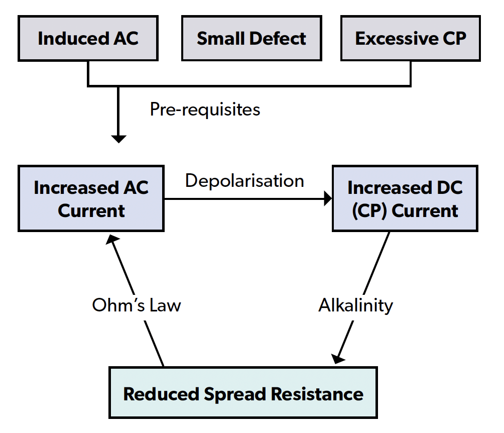
Figure 3 – Autocatalytic Nature of AC Corrosion on Cathodically Protected Pipelines Described by Sp21424.
As shown in Fig.3, the AC current density can lead to the depolarisation of the defect: this requires a higher DC current density to maintain a certain cathodic protection potential. Increasing the level of cathodic protection to mitigate AC corrosion, in this case, has the opposite effect: the increase in DC current density further decreases the Spread Resistance at the coating defect due to the production of OH- ions (alkalinisation). Through high levels of cathodic protection, the Spread Resistance decreases, thus increasing the density of alternating current, restarting the cycle: this scenario results in an autocatalytic cycle leading to AC corrosion.
It therefore becomes clear that, in order to leave this cycle, it is necessary to control both the AC current density and the DC current density.
Analysis of A Real Field Case
The case that will be shown has been detected on a measurement point of the distribution network of a large European city, with the following features:
• An extensive cathodic protection system forming a ring around the city center with radiating offshoots.
• Multiple crossings with DC powered railways and surface metro.
• Multiple parallels with the HVAC network.
• Cathodic Protection guaranteed by two T/Rs.
The analysed measuring point (MP):
• Located in a CP system area with several km of parallelism with HVAC line. • Local soil resistivity between 25 and 50 Ω·m. • Equipped with permanent CSE reference electrode with integrated 10 cm² coupon (measured current density is underestimated compared to 1 cm² coupon). • Equipped with a G4C-PRO remote monitoring device capable of performing instant-off measurements on coupon and current density measures.
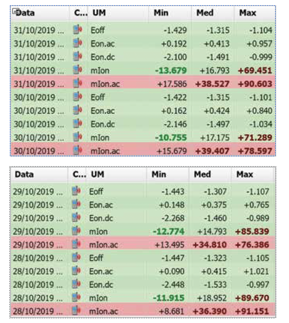
The measurements shown in Table 1 correspond to daily reports calculated on measurements performed continuously at a frequency of 1 Hz (1 measure per second) for each measuring channel. The minimum, average and maximum daily values are shown over a period of 4 days:
• Eon.dc: ON potential (DC) expressed in V CSE; • Eon.ac: ON potential (AC) expressed in V; • E off: instant-off on coupon, equivalent to IR-Free potential (measured, every second, after a 1 ms wait from switch opening and over a 20 ms interval) expressed in V CSE; • mIon: DC polarisation current of the coupon expressed in mA; as the coupon size is 10 cm2 the shown value corresponds to the current density in A/m2; • mIon.ac: AC polarisation current of the coupon expressed in mA; as the coupon size is 10 cm2 the shown value corresponds to the current density in A/m2 (note: the current density value measured on a 1 cm2 coupon would be significantly greater than that measured on the 10 cm2 coupon).
In the absence of coupons, the only available measures would be Eon.dc and Eon.ac, and, on these values, the only possible evaluation would be that relating to the first step of ISO 18086, which would be absolutely respected considering that the highest AC average value along the four days shown (0,424 V) is well below the indicated threshold of 15V. Generally, such a low AC voltage value would never suspect a real risk of AC corrosion, but as can be detected from the DC and AC current densities, we are faced with unacceptable interference levels:
• mIon: between 15 A/m2 and 17 A/m2:
o greater than the threshold of 1 A/m2 for which (according to ISO 18086) the AC current density value would be indifferent.
• mIon.ac: between 35 A/m2 and 39 A/m2:
o greater than the threshold of 30 A/m2 indicated by ISO 18086 and NACE SP21424.
The explanation for this situation is given precisely by the significant level of cathodic overprotection present, represented by IR-Free potential values more negative than -1.3 V CSE and very high DC current density values, being the MP in a site suffering cathodic DC interference generated by metro and railway systems.
This results in a reduction of the Spread Resistance value, up to the point of generating an AC current density higher than the allowed limits even in the presence of a very low AC voltage.
The main evidence of the dependence of this condition on over-protection has been clearly shown when, due to a malfunction, one of the two T/Rs protecting the Cathodic Protection system did shut down, changing the values measured on the Measurement Point as in Table 2:
Hani Almufti, Technical Lead, Cogbill Construction (RedLineIPS), USA.
Meet the Author
Hani Almufti is Engineer and Manager of Strategic Development at Cogbill Construction (RedLineIPS), where he leads product strategy, materials selection, and technical guidance for metallic and non-metallic pipe support systems. He holds a B.S. in Industrial Engineering and is a Master’s candidate in the same field. With 15+ years in pipe supports—including a decade focused on offshore energy corrosion—he specialises in corrosion under pipe supports (CUPS) and the performance of FRP/composite and metallic supports. His expertise spans corrosion mitigation, reliability engineering, and process improvement, with a sustained focus on reducing risk, noise/vibration, and lifecycle cost across onshore and offshore assets.
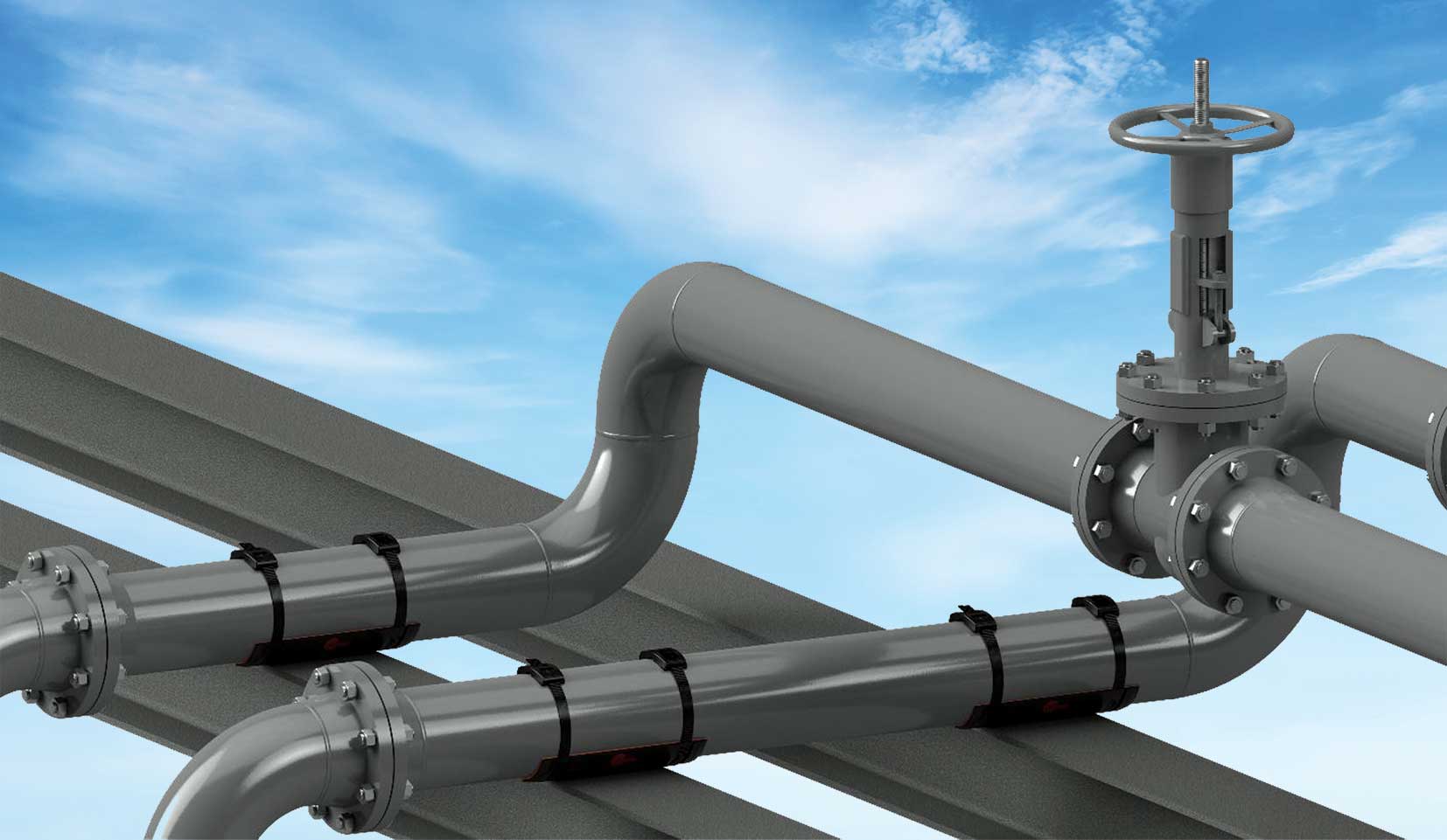
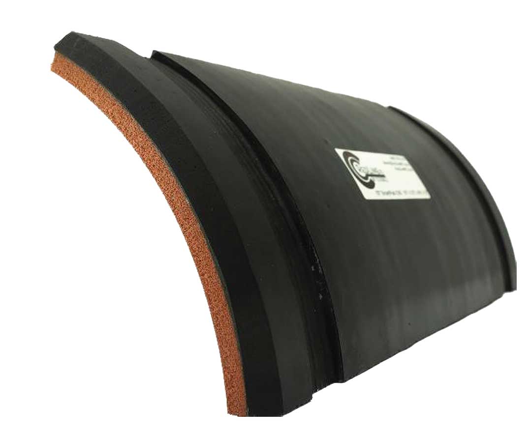
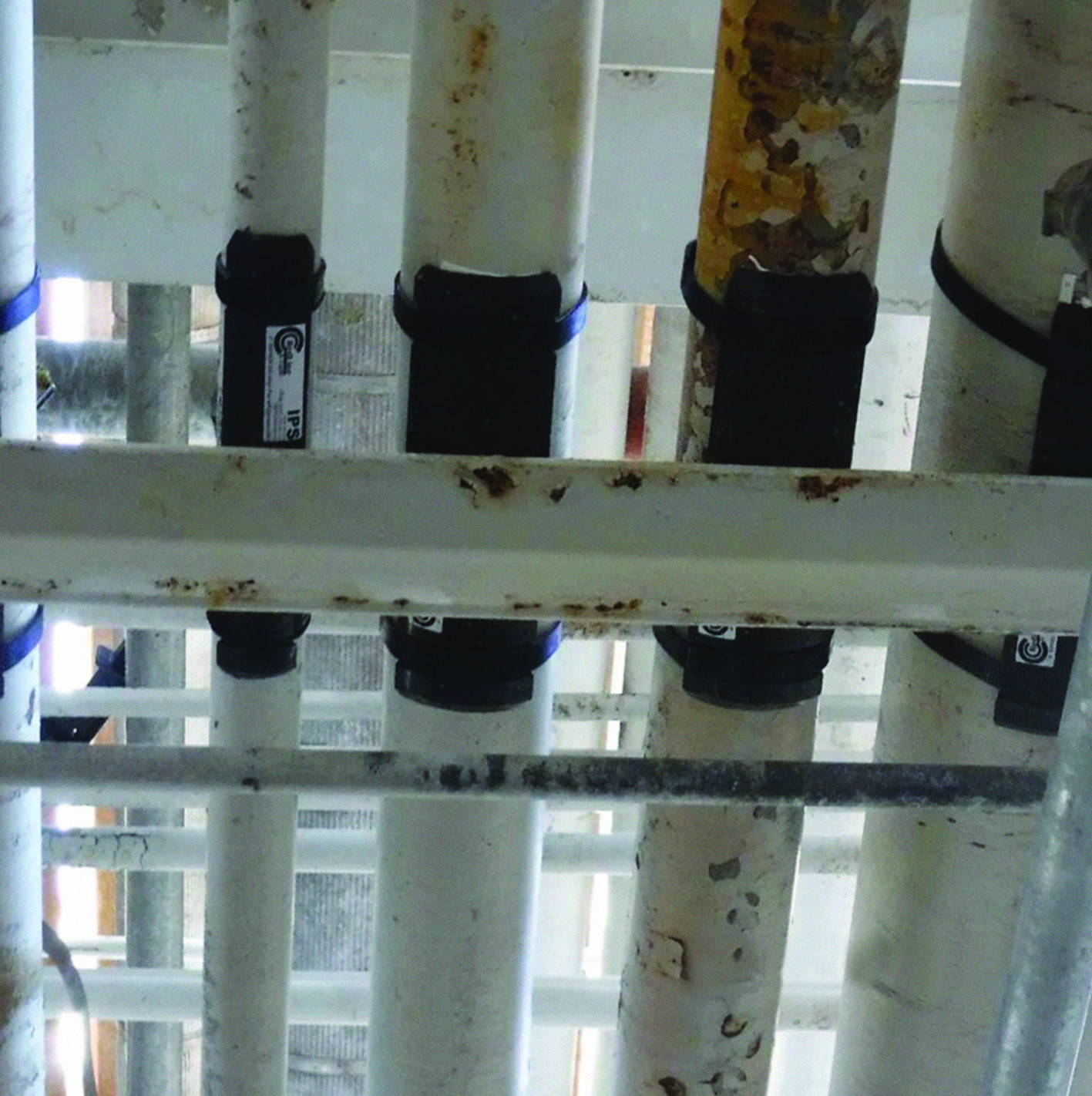
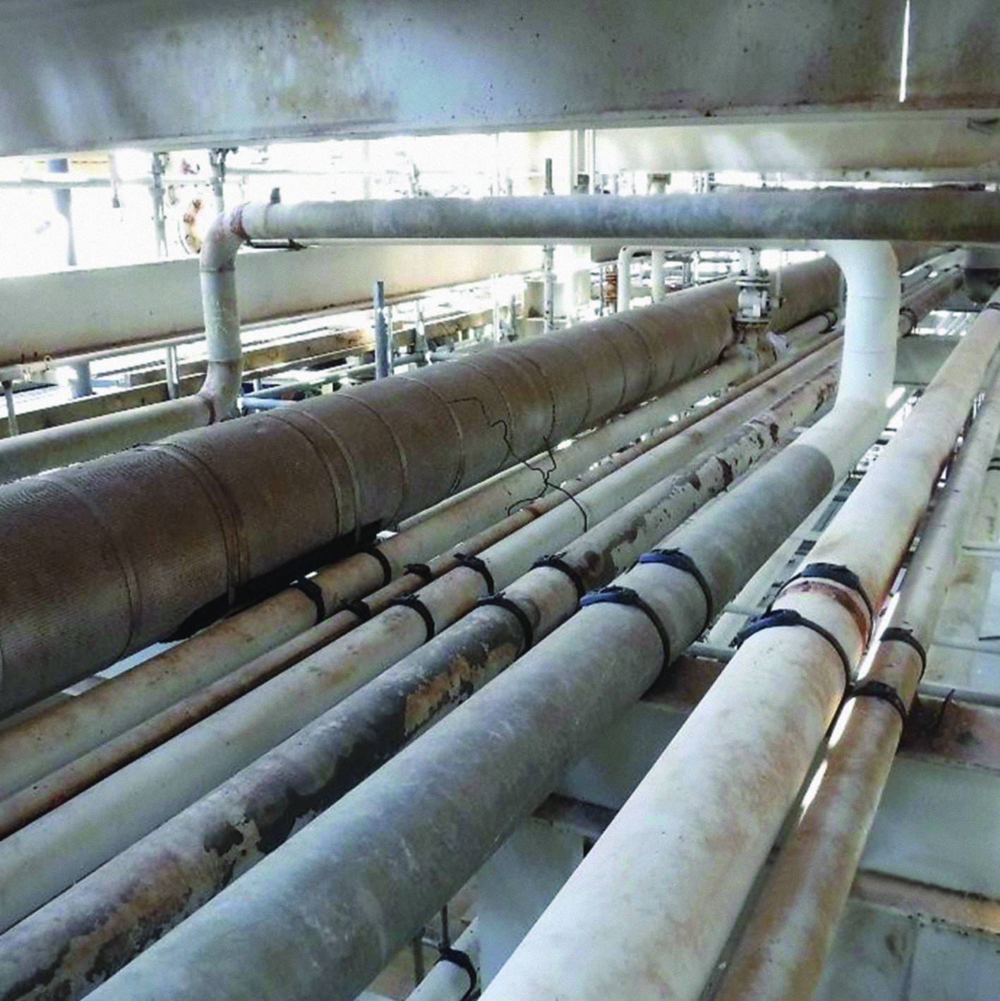
Photo 1: Installed System On Pipe Gantry.
1. Introduction
Pipe-support interfaces are convergence points for several degradation modes in industrial and offshore piping: corrosion under pipe supports (CUPS), vibration, structure-borne noise, and fatigue. On offshore platforms and FPSOs, major operators have reported that these risks are heightened by salt-laden atmospheres, hull motion, and restricted access, while the pipe–pad contact remains difficult to inspect [1].
Conventional mitigations—welded metallic pads, thermoplastic half-rounds, and epoxy-bonded plates—can re-establish galvanic paths, trap electrolyte, or require hot work and cure time. Maintaining seal integrity, alignment, and controlled slip becomes increasingly challenging as coatings wear and thermal cycles accumulate [1]. The RedLineIPS SmartPad System is a fully non-metallic support interface comprising a load-spreading FRP saddle, a bonded closed-cell elastomeric gasket (Hydroseal), and FRP bands/buckles.
Together, they electrically isolate the pipe from the steel support, seal the pipe–pad contact to discourage moisture films, provide viscoelastic damping at the interface, and relocate thermal slip to a controlled, low-friction plane on the saddle/support side. This paper outlines the design rationale, installation approach, and third-party proofs, and summarises field experience from a Gulf Coast of Mexico chemical plant retrofit programme.
2. The SmartPad System
2.1 Composite FRP SmartPad (Saddle Wear Pad) 2.1.1 Construction and geometry Structural fibre-reinforced polymer (FRP) saddle fabricated from continuous-strand mat (CSM) in a vinyl-ester matrix, moulded to standard pipe curvatures of 1/2” to 72” NPS. The crown radius and contact width are sized to spread load over a broad arc, keep local bearing pressure low, and maintain stable seating under thermal and dynamic loads.
2.1.2 Functions at the pipe–pad interface • Load distribution: Spreads the pipe’s weight over a wider area so no small spot takes all the pressure—reducing dents and coating damage.
• Electrical isolation: Non-conductive composite interrupts metal-to-metal continuity (limits galvanic coupling to support steel).
• Coating protection: Smooth, inert bearing surface reduces abrasion during thermal slip and vibration.
• Continuous service temperature: -60°F to 400°F (-51°C to 204°C).
• UV resistance: High (integral inhibitors).
• Fire behaviour: Fire-retardant formulation (rating available on request).
2.1.4 Manufacture and Integration
Hand lay-up with controlled cure to achieve low void content and uniform fibre wet-out. Finished edge radii and surface roughness are controlled to minimize coating gouge. Saddle curvature and contact-width tolerances support repeatable fit and clamp preload. The FRP saddle provides the load-bearing, isolating substrate for the bonded closed-cell gasket and FRP banding within a fully non-metallic load path.
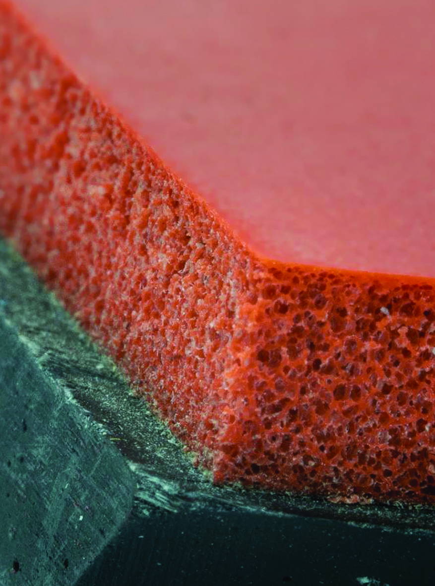
2.2 Hydroseal Closed-Cell Gasket
Photo 3: FRP Saddle and Closed Cell Gasket.
2.2.1 Construction and Placement
Factory-bonded to the SmartPad’s pipe side, the closed-cell elastomer compresses under band preload to form a continuous, conformal contact that accommodates normal surface roughness and remains uniform through thermal and vibration cycles at the pipe–pad interface.
2.2.2 Functions at the Pipe–Pad Interface
• Moisture Exclusion / CUPS Control: Very low water uptake; compressed contact suppresses crevice geometry and ion/oxygen transport, limiting crevice/under-deposit and MIC precursors.
• Vibration and Noise Attenuation: Viscoelastic damping lowers transmitted shear and micro-slip; the compliant, non-metallic layer acts as an acoustic impedance break to reduce structure-borne noise and alternating stress.
• Assists Galvanic Isolation: In combination with the FRP saddle, maintains a fully dielectric contact path.
• Operating temperature: –60°F to 570°F (-51°C to 300°C) • Compression-set resistance: Excellent
2.2.4 Durability and Integration
Under FRP-band preload, the gasket maintains stable compression, preserving seal and damping through thermal/vibration cycling and tolerating minor surface irregularities from prior repairs. Within the fully non-metallic load path, the gasket supplies sealing, compliance, and energy dissipation that complement the saddle’s stiffness and protect the coating at the pipe–pad interface.
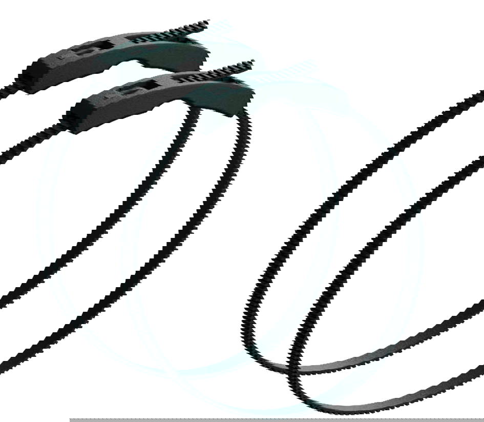
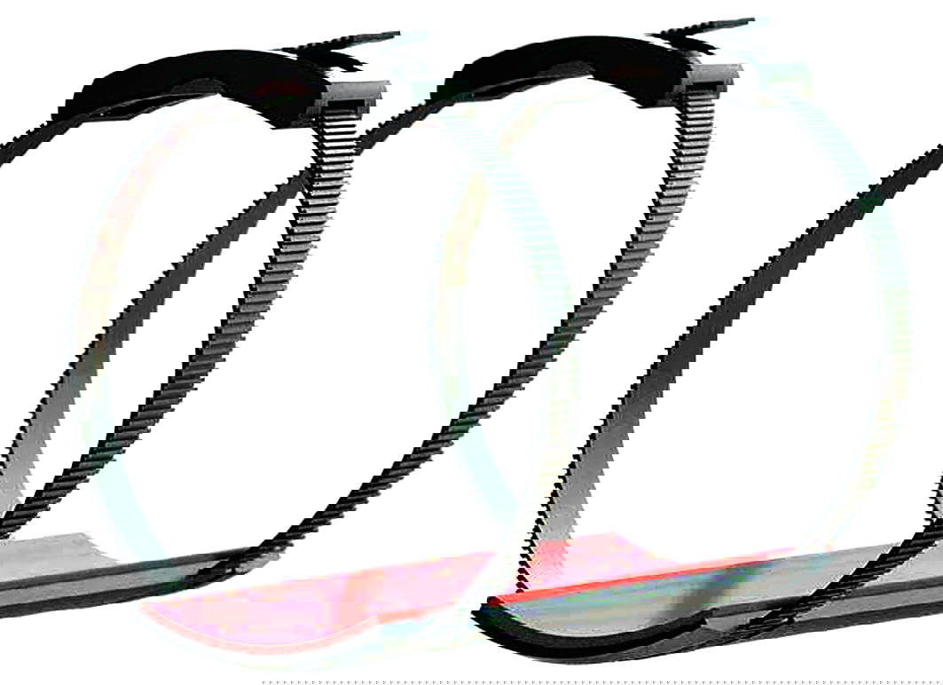
2.3 SmartBands
2.3.1 Construction and Locking
Continuous long-strand FRP straps in a UV-resistant resin, paired with a matching-pitch FRP square-tooth buckle for incremental, non-backdrivable engagement. Radiused edges and smooth faces limit stress risers and coating damage.
• Preload delivery/retention: Long-strand reinforcement improves load transfer and creep/fatigue resistance, maintaining clamp force through thermal and vibration cycling.
• Surface compatibility / constructability: Non-marring inner face; smooth outer face for clean tensioning. Installs with a calibrated handheld tool—no hot work or adhesives.
• Thermal range: –40 °F to 250 °F (–40 °C to 121 °C).
• Electrical behaviour: Dielectric, non-metallic.
• Environmental durability: Corrosion-immune; outdoor/UV rated for coastal/offshore service.
2.3.4 Installation and Preload Control Bands routed in moulded circumferential grooves in the saddle engage the FRP buckle and are tensioned to specification with a calibrated tool. Groove geometry sets bend radius, keeps the strap flush/recessed, and prevents lateral migration; the low-profile routing avoids snagging and maintains uniform bearing. Preload is confirmed by tool indication (or witness marks). For underside inspection, bands are single-use—they are cut and replaced with new bands; replacements are low-cost, and reinstallation typically takes minutes per support. Grooved routing also localises relative motion to the engineered slip plane at the saddle–support interface [4].
2.3.5 Durability and Integration The continuous-strand architecture resists creep and tooth-root fatigue under cyclic loads. UV-stabilised resin supports long outdoor exposure; the all-composite assembly is unaffected by chloride corrosion. SmartBands provide the clamping force that maintains the Hydroseal seal and the saddle’s load-sharing contact within a fully non-metallic load path.
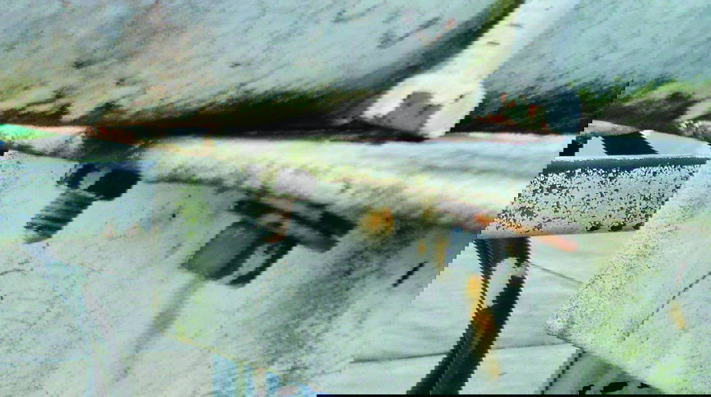
Photo 5: Example of Corrosion Under Pipe Support.
3. Corrosion Mechanisms at Support Interfaces
3.1 Crevice / Differential Aeration
Mechanism: A narrow, shielded gap at the pipe–pad interface traps a thin electrolyte. Oxygen is depleted inside the gap while adjacent surfaces remain aerated, creating an anode/cathode differential. Wet–dry cycling concentrates chlorides and lowers pH, undermining coatings and accelerating localised metal loss [1].
SmartPad Mitigation: A factory-bonded, closed-cell Hydroseal gasket forms a continuous conformal contact under preload, denying voids where films persist. The FRP saddle spreads load to keep contact pressure uniform through thermal cycles, disrupting the differential-aeration cell associated with CUPS.
3.2 Galvanic at the Support
• Mechanism: Electrically coupled dissimilar (or conditionally different) metals sharing an electrolyte drive anodic dissolution; small-anode/large-cathode area ratios intensify attack at supports [1].
• SmartPad Mitigation: A fully dielectric load path—FRP saddle, Hydroseal gasket, and FRP SmartBands™/buckles—breaks metal-to-metal continuity. The sealed interface also limits shared electrolyte, cutting off both prerequisites for galvanic corrosion.
3.3 Microbiologically Influenced Corrosion (MIC)
• Mechanism: In intermittently wet crevices, biofilms (e.g., SRB) create chemically distinct microenvironments (sulfides, acidity, differential aeration) that localise attack
[1]. • SmartPad Mitigation: The low-uptake, closed-cell contact shortens wet-film residence time and reduces attachment sites. Smooth, non-porous, electrically isolating surfaces further discourage biofilm establishment and persistence at the pipe–pad interface.
3.4 Fretting-Assisted Corrosion
• Mechanism: Sub-millimeter relative motion from vibration/thermal cycling abrades coatings and oxides; freshly exposed steel corrodes between slips, forming a wear–corrosion feedback loop focused at the supports [1].
• SmartPad Mitigation: Viscoelastic damping in Hydroseal stabilises the pipe–pad contact and lowers micro-slip. Required thermal movement is relocated to the low-friction saddle–support interface, while the FRP saddle’s load distribution reduces shear at the pipe wall.
3.5 Under-Deposit/Capillary Thin-Film
• Mechanism: Deposits or capillary-held films trap chloride-rich, oxygen-poor moisture that behaves like a crevice beneath the footprint [1].
• SmartPad Mitigation: The bonded, continuous interface leaves no seam for solids to wedge; closed-cell elastomer resists wicking. Moisture remains on exposed, cleanable surfaces rather than beneath the pipe.
4. Vibration
4.1 Sources and frequency content Piping vibration originates from rotating/reciprocating equipment (pumps, compressors, blowers), pulsation in positive-displacement services, turbulence at fittings/reducers, two-phase/cavitation, hydraulic transients, alignment/soft-foot issues, and support stiffness mismatches. Field spectra commonly fall in the 10–100 Hz band with ~0.25–2.5 mm (0.01–0.10 in) peak-to-peak motion; response amplifies near span/support natural frequencies (cf. ISO 20816-1) [5].
4.2 Why the pipe–pad interface matters Rigid, metal-to-metal load paths transmit dynamic energy as micro-slip and contact shear at the pipe–pad interface. This accelerates coating wear (promoting CUPS), excites support steel (structure- borne noise), loosens hardware, and increases alternating stress Δσ—shortening fatigue life per S–N behaviour.
4.3 SmartPad mitigation mechanisms • Interface damping (Hydroseal). The closed-cell elastomer provides viscoelastic damping in the 10–100 Hz range, reducing transmitted shear/micro-slip and smoothing contact pressures [6].
• Relocated slip (FRP saddle). The moulded saddle furnishes a controlled, low-friction slip plane at the saddle–support interface so thermal movement does not abrade the coating at the pipe–pad interface; broad bearing further lowers work per cycle.
• Stable dielectric clamping (SmartBands™ in recessed grooves). Calibrated, all-composite preload maintains uniform contact without re-introducing metallic short circuits, low-profile routing resists lateral migration and secondary rattles.
5. Sound (Structure-Borne Noise)
5.1 Mechanism Dynamic forces excite the pipe wall; a rigid, metal-to-metal path at the pipe–pad interface transmits that energy into support steel and deck members, which then radiate airborne noise. Frictional micro-slip at a hard contact can also generate “stick–slip” (squeal) components. Acoustic transmissibility rises when the interface impedance closely matches the supporting structure.
5.2 Sources and Frequency Content The same drivers as vibration—rotating/reciprocating equipment, pulsation in positive-displacement (PD) services, turbulence, two-phase/cavitation, hydraulic transients, alignment/soft-foot, and support stiffness issues—dominate. On process/offshore lines, most structure-borne content is ~20–200 Hz, overlapping habitability and communication bands
[5]. 5.3 SmartPad Noise-Control Mechanisms
• Impedance break + damping (Hydroseal): The closed-cell elastomer introduces a compliant, non-metallic layer at the pipe–pad interface, lowering mechanical impedance and adding viscoelastic loss. Result: reduced transmissibility and less friction-generated noise from micro-slip.
• Controlled slip on the support side (FRP saddle): The moulded FRP surface provides a low-friction slip plane at the saddle–support interface, keeping relative motion off the coating and suppressing stick–slip at the pipe–pad contact. Broad bearing further lowers contact forces that drive radiation.
• Dielectric, Low-Profile Clamping (SmartBands in recessed grooves): All-composite bands maintain the decoupled path (no metallic short-circuit) and sit flush to avoid secondary rattles; calibrated preload keeps contact uniform.
6. Structural Integrity (Fatigue & Stability)
6.1 Overview The pipe–pad interface largely governs fatigue performance at supports. A hard, rigid contact concentrates routine loads and transmits vibration into repeatable stress cycles, leading to local denting, coating loss, misalignment, and ultimately crack initiation in the pipe wall or supporting steel [7].
6.2 Principal contributors at supports • Thermal restraint. Limited slip forces the pipe to bear against the interface; daily temperature swings add alternating load.
• Small real contact area / edges. Narrow bearings or sharp transitions elevate local pressure and seed dents.
• Dynamic excitation. Equipment- and flow-induced vibration increases the stress range each cycle.
• Fit-up variability. Misalignment or uneven bearing amplifies local stress and accelerates coating abrasion.
6.3 Why this matters for fatigue
Fatigue life follows S–N behaviour and is controlled by the alternating stress amplitude (Δσ). Dents, coating scrapes, and other stress raisers reduce cycles to initiation; once the coating is breached, corrosion further degrades the section, compounding risk [7].
6.4 SmartPad mitigation mechanisms
• Load distribution — FRP saddle. Broad bearing lowers peak contact pressure and mitigates edge effects; the non-conductive substrate avoids metal-to-metal paths that undermine coatings.
• Compliance & damping — Hydroseal gasket. A firm, closed-cell elastomer equalises contact pressure, absorbs vibration, and cushions small impacts, reducing contact shear and Δσ per cycle [6].
• Controlled movement without abrasion — saddle–support slip plane. Thermal growth is taken on the moulded FRP surface (optional low-μ liner if needed), minimising stick–slip and fretting at the pipe–pad contact.
• Stable alignment & clamp — SmartBands in recessed grooves. Calibrated, all-composite preload keeps contact uniform and resists lateral migration; the dielectric, low-profile routing avoids galvanic short-circuits and loose hardware. (For underside inspection, bands are single-use—cut and replaced; this is a low-cost operation).
Photo 6: Full System Assembly.
7. Third-Party Testing: SmartPad Suitability for Industrial Service
Independent third-party testing was performed on specimens, as follows:
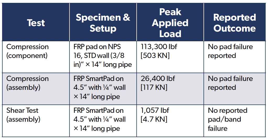
7.1 Results – Proof Loads, No Failures Observed
• Pad-only Compression: FRP saddle on NPS 16, STD wall pipe sustained 113,300 lbf axial compression without pad failure.
• Assembly Compression: Banded SmartPad-on-pipe (4.5 in OD × ¼ in wall) sustained 26,400 lbf axial compression without pad failure.
• Assembly Shear: Same assembly sustained 1,057 lbf lateral (shear) without pad or band failure.
7.2 Interpretation For the geometries/fixtures tested under monotonic loading, neither the composite saddle nor the banded assembly was the limiting element. The components tolerated high localised bearing and incidental lateral restraint typical of pipe-support reactions when installed and preloaded to specification.
7.3 Scope and Limits These are static proof tests on short specimens. They do not establish design allowables or characterise fatigue, creep/relaxation, or environmental durability. Apply normal owner engineering practices (codes, load combinations, temperature, vibration/fatigue assessment) [8,9].
7.4 Implication for Use Combined with the corrosion mechanisms described in section 3 (sealed dielectric interface, viscoelastic damping at the pipe–pad contact, and load spreading/controlled slip), the proofs support the SmartPad System’s mechanical suitability as a non-metallic pipe-support interface for industrial and offshore service, subject to project-specific engineering review.
8. Case Study — Coastal Texas Chemical Plant (Anonymised)Background
A large Gulf Coast complex retrofitted the RedLineIPS SmartPad System to mitigate CUPS, structure-borne noise, and nuisance vibration at pipe/support interfaces in a salt-laden, high-humidity environment.
8.1 Scope
• Units: Olefins recovery, utilities/cooling water, brine handling.
On the 2nd December 2025, the Institute of Corrosion (ICorr) was proud to serve as a sponsor of the prestigious 72nd Hatfield Memorial Lecture, https://sheffield.ac.uk/cmbe/school/events/72nd-hatfield-memorial-lecture hosted at the University of Sheffield. ICorr’s President, Dr Yunnan Gao, attended the event on behalf of the Institute, demonstrating ICorr’s ongoing commitment to supporting academic excellence and advancing corrosion and materials science across the UK.
A Distinguished Lecture Delivered by ICorr Fellow Professor Mary Ryan
This year’s lecture was delivered by Professor Mary Ryan, CBE, FREng, FICorr, a Fellow of ICorr and Vice Provost (Research and Enterprise) at Imperial College London, https://www.imperial.ac.uk/about/leadership-and-strategy/provost/vice-provost-research/ who is renowned globally for her work in corrosion, surface engineering, and nanomaterials. Professor Ryan offered an insightful and forward-looking presentation entitled “Life and Death at the Nanoscale” that captured the attention of industry experts, academics, and students alike.
Her lecture continued the long-standing tradition of the Hatfield Memorial Lecture series, which honours metallurgist Professor William Hatfield and has become a cornerstone event for the UK materials and corrosion community.
Presentation of the Hatfield Award
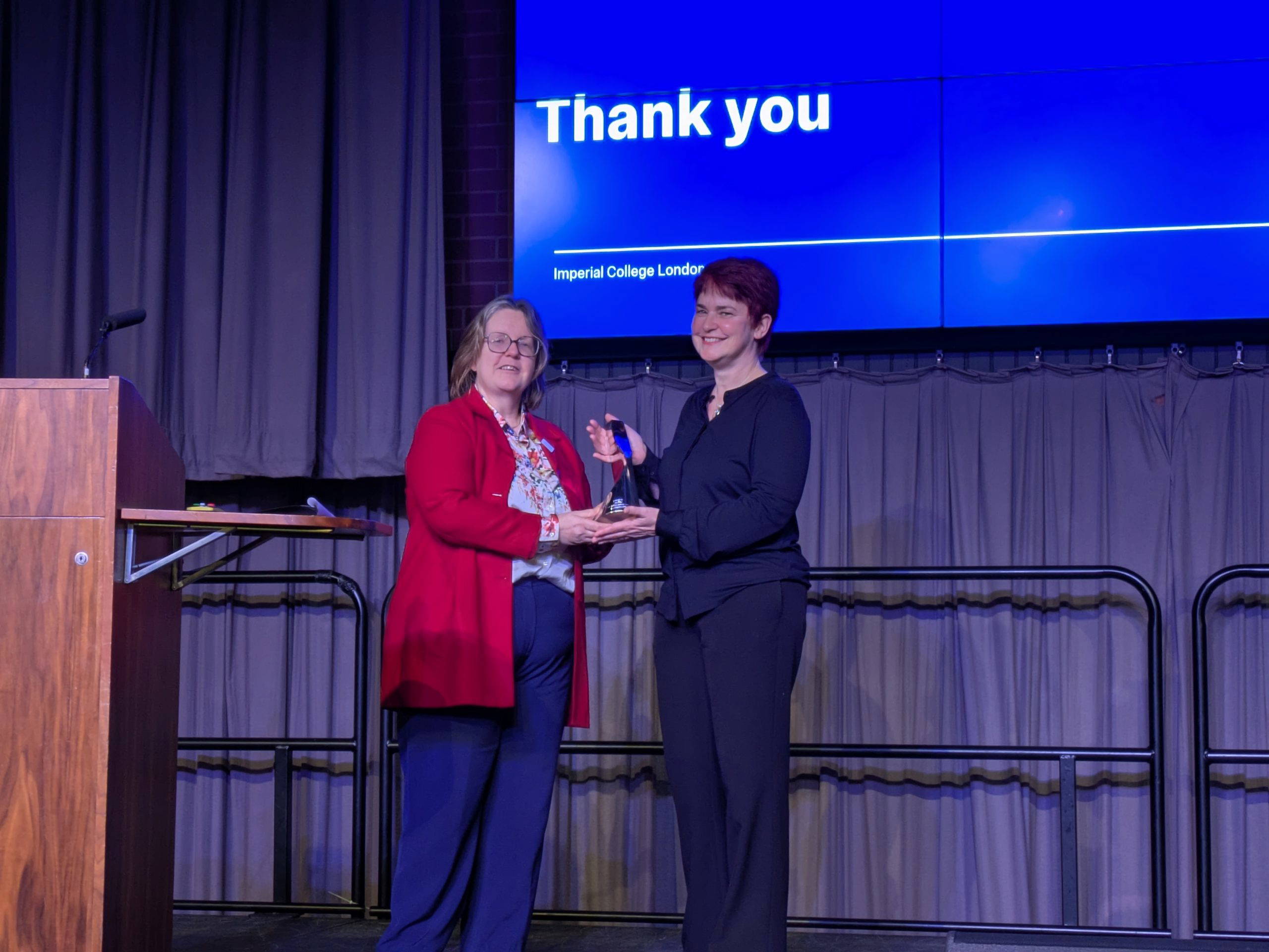
During the event, Professor Mary Ryan was formally recognised for her significant academic and professional achievements. She received a commemorative award presented by Professor Joan Cordiner, Head of the Department of Chemical and Biological Engineering (CMBE) at the University of Sheffield, marking a highlight of the evening.
ICorr’s Role and Presence at the Event
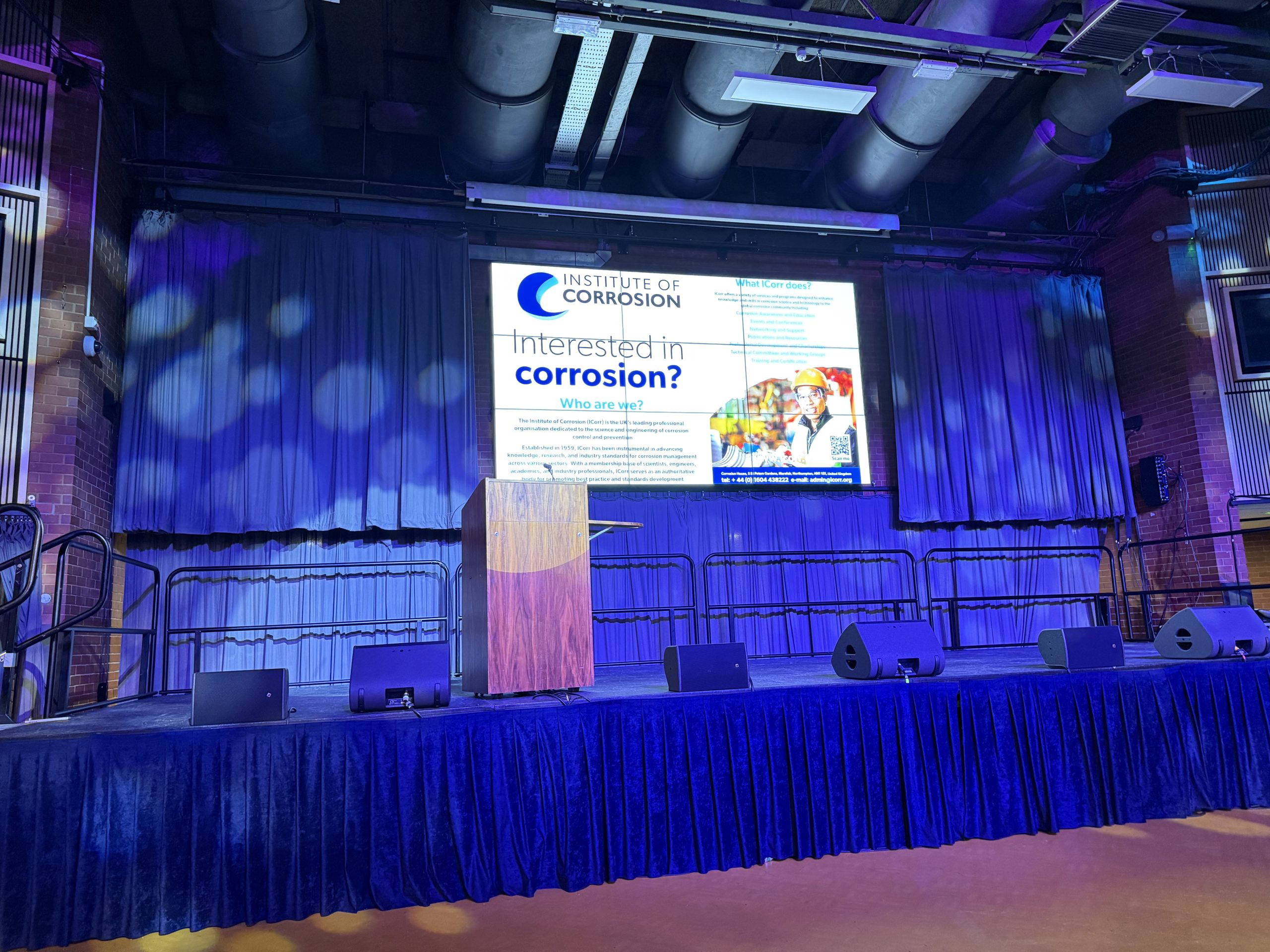
As one of the official sponsors, ICorr’s support was prominently acknowledged throughout the night, including on the main auditorium screen and event materials. The presence of the ICorr President reinforced the Institute’s mission to promote collaboration, scientific excellence, and knowledge exchange across the corrosion and materials community.
ICorr’s involvement with the Hatfield Memorial Lecture reflects its dedication to fostering innovation and supporting both established and emerging experts in the field.
Overview of the Venue of The 72nd Hatfield Memorial Lecture
Professor Mary Ryan of Imperial College London Delivering The 72nd Hatfield Memorial Lecture
Hatfield Award Received by Professor Mary Ryan from the Head of the CMBE of Sheffield University
ICorr is One of the Sponsors of the The 72nd Hatfield Memorial Lecture
We use cookies to optimize our website and our service.
Functional
Always active
The technical storage or access is strictly necessary for the legitimate purpose of enabling the use of a specific service explicitly requested by the subscriber or user, or for the sole purpose of carrying out the transmission of a communication over an electronic communications network.
Preferences
The technical storage or access is necessary for the legitimate purpose of storing preferences that are not requested by the subscriber or user.
Statistics
The technical storage or access that is used exclusively for statistical purposes.The technical storage or access that is used exclusively for anonymous statistical purposes. Without a subpoena, voluntary compliance on the part of your Internet Service Provider, or additional records from a third party, information stored or retrieved for this purpose alone cannot usually be used to identify you.
Marketing
The technical storage or access is required to create user profiles to send advertising, or to track the user on a website or across several websites for similar marketing purposes.