A Critical Assessment of The Half-Life  Ageing Term and Failure to Predict  Future Galvanic Anode Behaviour

A Critical Assessment of The Half-Life Ageing Term and Failure to Predict Future Galvanic Anode Behaviour

Meet The Authors

Christian Stone, M.S., M.Phys., is a corrosion scientist and technical expert at Concrete Preservation Technologies (CPT) who specialises in the development of next-generation corrosion management systems, supports the use of cathodic protection worldwide, and is a leading expert in corrosion in RAAC concrete. Christian sits on a number of professional organisations, is a member of the Loughborough University RAAC Research Team and is currently undertaking further research on RAAC with Loughborough University.

Gareth Glass is a Director at Concrete Preservation Technologies (CPT), a position he has held since the inception of the company in 2005.  He has extensive experience in materials technology, durability and rehabilitation of structures with over 100 publications to his name in the area of corrosion protection. He obtained his PhD from the Corrosion and Protection Centre, University of Manchester.

Introduction

The term ‘ageing factor’ (sometimes referred to as ‘ageing constant’) for galvanic Anodes, was first coined by Sergi et al in ‘Monitoring results of galvanic anodes in steel reinforced concrete over 20 years’ in Construction and Building Materials, 2020 [1]. The principle behind this idea is that discrete measurements of galvanic current data from precast anode systems, when plotted on a logarithmic graph, could be fitted with a straight line. Therefore, they claim that their anodes exhibit a ‘half-life’ model with the current trending to zero, halving over set time intervals, the ‘ageing factor’. They further claim that when the anodic current density falls below a threshold, the anodes no longer adequately protect the steel reinforcement.

Modelling – Apparent Discrepancies

The first site analysed by Sergi et al. was a bridge in Leicester; current was measured. approximately 26 times for 12 individual patch-anodes from a single patch over 20 years. The initial description of the anodic current describes three distinct stages of relatively stable current output, each below the prior level: 0-6 years, 7-14 years and 15-20 years. This was described, at least in part, due to a drop in pH of the pore solution of the electrolyte. A half-life ageing constant of approximately 7 years over which the current would half was then generated by the plotting of the current readings on a logarithmic scale and a straight line being fit to the data [1]. The reason for the choice of a logarithmic scale is not fully explained, with decreases in surface area and depletion of lithium hydroxide being cited.

This concept was furthered in the next year in the Journal of Building Engineering (June 2021) [3], at the Corrosion Conference (November 2021) [4], Structural Faults and Repair Conference (2022), an ICRI webinar, ’Design Considerations for Galvanic Anodes’ (December 2022) [5], in the book Life-Cycle of Structures and Infrastructure Systems [6], and 3rd Conference & Expo Genoa (2024) [7]. Throughout these publications, ‘ageing factors’ were published for approximately 12 elements using precast Vector Corrosion Technologies (VCT) anodes and their precast precursors, and included both site and laboratory data. Of particular note was the ICRI webinar and the AMPP Italy Corrosion Conference white paper, where the half-life style ‘ageing-factor’ hypothesis was applied to non-precast anodes manufactured by other companies, including Concrete Preservation Technologies (CPT) and an ‘ageing factor’ was published for CPT’s hybrid anode, one that is initially powered externally before being wired galvanically, the DuoGuardTM anode system [5,7]. The predicted ‘ageing constant’ published for these anodes was 2.9 years, and was compared unfavourably to the 11 year ‘ageing factor’ for their own products.

There were however, some significant changes made to use of this empirical model. Rather than being a model for some precast patch anodes manufactured by a single company and their precursor anodes the hypothesis was now being applied to anode arrays cast with a different geometry, embedded in a different cementitious material, located in the host concrete rather than a patch, and very importantly not activated using the same chemistry that was cited as a major cause of the exponential decay in the original paper [1]. DuoGuardTM is activated chemically in such a way that the activator is not depleted but recycled, continually drawn back to the anode. Therefore, the theoretical underpinnings cited by the authors do not appear to hold for these anodes. This has led to the need for a closer look at this model and whether it can tell us anything about the behaviour of these anode systems or whether the model can reliably predict the behaviour of CPT anodes.

In order to understand this model, it is important to first explore the stated and hidden axioms behind the hypothesis and how these lead Sergi, Whitmore and others to interpret their data in such a way. In this section, we will place to one side the fact that there is no stated theoretical underpinning to the choice of a logarithmic scale and allow for the strength of the predicted current data to judge
its veracity.

Half-Life Theory Axiom – There is A Set, Minimum Current Threshold For the Protection of Steel In Concrete

The corrosion risk of steel is due to its environment. This should be a relatively uncontroversial statement, as it is known that steel in fresh concrete is passive and requires no cathodic protection, and steel in carbonated concrete has a lower corrosion rate on average than steel in chloride-rich environments [8]. Furthermore, corrosion rates can vary due to the exposure to moisture, availability of oxygen and be changed by coatings applied to the steel. It is therefore reasonable to assume that the amount of protection steel in concrete requires for protection is a product of its environment.

Although the authors do acknowledge the importance of chloride in the amount of current needed to protect steel in concrete [7], they ignore many of the other factors. This inherent complexity is why it is often much easier to measure changes in the steel due to protection rather than purely the current output of the system. Such measurements are common with impressed current cathodic protection (ICCP) systems that use ISO 12696:2021 [9], which gives steel potentials in the immune region and polarisation held in the steel. originating from Mixed Potential Theory [10,11], as criteria for protection. Within galvanic cathodic protection (GCP), it is  common to track the depolarised steel potentials [12] to measure changes in corrosion risk, polarisation [13] and corrosion rates [14,15]. These measure the effect of the anodes on the steel rather than the output alone to determine the level of protection achieved.

Comparison of Anode Systems

This is further complicated by the fact that some anode systems are installed in different ways, leading to varied current spread. It matters very little how much current an anode produces if it is not reaching the at-risk steel it is installed to protect. To explain this concept more clearly, two anode systems for patch repair will be compared: a precast anode designed to be tied onto the reinforcement in a patch and a patch anode that is installed into a putty in the periphery of the patch, away from a single steel rebar. Below CPTs precast anode RebaGuardTM and drilled anodes PatchGuardTM can be seen. RebaGuardTM is similar to the anodes installed in many of the author’s works.

The steel being protected by patch anodes is the steel outside of the patch, as the steel in the patch is in fresh, alkaline, contaminant-free concrete. The precast anodes are tied to the steel within the patch. It is not difficult to see that it is likely that a large portion of the current will take the easiest path between the zinc and the steel, to the reinforcement onto which it is tied. The current that does exit the patch must avoid taking the easiest path, passing through the interface between the patch and the host concrete, which will have a resistance and spread to the steel outside of the patch which is at some distance from the anodes. These anodes can and do work, but it is unlikely that all the current they produce is available to the steel they are protecting.

The PatchGuardTM anode is installed into the periphery of the patch, in the host concrete into a conductive putty, much closer to the steel it is designed to protect. Unlike the precast anodes, it is not tied to a single reinforcement, and the current will therefore more easily spread to the at-risk reinforcement. Furthermore, due to the increased resistivity of most patch materials and the resistive interface of the patch making current flow into the patch more difficult, it will favour passing current to the steel outside the patch rather than within the patch. It is therefore logical to think that the current from this PatchGuardTM anode will protect the rebar much more efficiently than the precast anode. Having the same current requirement for each of these anodes is illogical.

The validity of their threshold may be tested using the author’s data. The first work published in this series was the 20-year data from a ‘bridge in Leicester’ [1]. This site is a site which staff at CPT is quite familiar, and many senior members of staff were present at the installation of these anodes. Though the paper claims that after 20 years that the anodes are reaching the end of their life, with the current output dropping under their threshold for protection at approximately 14.5 years. In a statement to the Cathodic Protection Association (CPA) from March 2023 by CPT [16], it was shown that in 2015, ten years after the installation of the anodes, there was cracking in the element following the line of the reinforcement extending from the repairs. This is not a measure of success in a galvanic anode system and shows a flaw in their current threshold.

Potential Measurement Error – Taking Current Data From A Responsive System

One of the most important concepts with galvanic anodes is their responsive behaviour [17,18]. The driving voltage, as long as the anodes are activated, is due to the galvanic series and therefore can be approximated as constant; the current delivered to the steel is therefore largely dependent on the resistivity of the electrolyte in the circuit, the concrete. So, when the concrete is wet, full of ions, warm, etc, the circuit has a lower resistance and the cell between the zinc and the steel produces a higher current. This is a part of the draw of these anode systems as they give a level of protection which changes with the corrosion risk of the environment.

One of the issues that comes with this fluctuation in current is that when the anode currents are measured infrequently without other corresponding data, such as the weather. Steel polarisation or natural steel potentials – the data can be misleading. Currents taken on wet and warm days may be much larger than those taken on dry and cool days, which can make seeing trends in current output difficult, unless Adequate data is collected.

Furthermore, anodes installed into wet patches, or into slow-curing putties may have initial currents which are atypical due to the moisture surrounding the anode, decreasing the resistance between the zinc and the steel. In CPT’s anode systems, the putty may take many years to cure, a design feature to initially provide a larger current to aid in the passivation of the steel due to the reduction reactions at the steel surface producing hydroxide ions.

This ageing constant generated for CPT DuoGuard anodes was created from a few data points using anodic current data from
only the first nine years of the galvanic protection [7]. This was during the period when the putty was curing. This may have led
to some inaccuracies in predicting the long-term behaviour of these anodes.

Whiteadder Bridge – Duoguard Hybrid
Anode System CASE Study

The data used by Sergi et al to calculate the ageing factor for DuoGuardTM anodes was taken from data published from Whiteadder Bridge in the UK [17].Here, two zones of anodes
were installed within a proprietary putty in regularly spaced,
drilled holes, and wired together to form arrays which protect the upper and lower portions of the structural element supporting the span of the bridge over a river. The anodes were installed to counteract the corrosion issues caused by de-icing salts and moisture ingress, including tidal flooding of the river.

The anodes were initially powered until at least 50kC of charge had been passed for every square meter of steel surface area to realkalise the steel environment, utilising the zinc’s ability to pass much higher currents than MMO titanium anodes when powered, and then connected directly to the steel via a junction box. Reference electrodes were installed in the zones, and the current output of the anodes alongside the reference potentials were measured by a data logger installed in an enclosure. This gives a constant stream of data, far in excess of those sites of similar ages used in the work by Sergi and Whitmore.

The element has been protected for 18.5 years now without the need for any maintenance beyond the replacement of SIM cards in the enclosure which transmit the data wirelessly to our office, and has been monitored with over 100,000 data points collected over the first 17.5 years of protection in each zone and over 1,000,000 data points collected in sum. The data used for the predicted 2.9-year ageing factor found in the AMPP Italy white paper [7] was taken from the first 9 years of data [17], which was not the most recent publicly available data set at the time [18] and appears to include only a small number of data points. It is unclear how these data points were selected. Due to the initial charging of the anodes, the authors claim that it would be expected that such anodes would likely have a decreased life due to having to pass a large amount of current early in their design life [7].

Although this model is now used in specifications and design documents worldwide, this will be the first predictive test of their empirical model and, importantly, a test of whether this model can be applied to anodes other than their own, for which they likely have a greater abundance of data. The aim of the following section is to analyse the predictive power of this model using data from the CPT site used in their analysis using the most recent data collected which presumably they had little access to.

Site Data – Responsive Behaviour

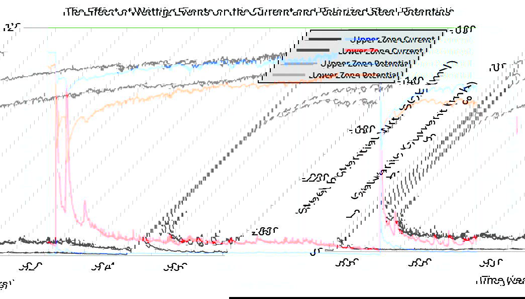
Below are the current and the polarised steel potentials for the lower zone of anodes installed on Whiteadder Bridge above, the same data used in the author’s work [7,17], but now with an additional 8 years of data. The red line is the galvanic current data showing the characteristic responsive behaviour with currents rising and falling in yearly cycles due to temperature changes and peaking during periods of increased moisture due to rainfall or flooding. This supports the theory that current is being driven in these anodes due to changes in resistance in the concrete electrolyte. The blue line is the polarised steel potential. When the current increases, we see a corresponding peak in the steel potential as the current generates a polarisation in the steel. Polarisation is a sign of steel passivity, with more passive steel polarising more easily than corroding steel. A green line has been added to show that over time the steel potentials are trending less negative, an indication of increased steel passivity.

The first few years of the data do show an increased current output from the anodes. As was previously stated, this is likely due to the putty into which the anodes were installed curing. After this period, the current appears to become more stable and respond to changes in resistivity from a relatively stable baseline. Taking a closer look at the data from around 9 years after installation, we can see the current from both zones increases due to fluctuations in temperature during the day as well as throughout the year. This response to corrosion risk with increased protection is one of the hallmarks of a naturally smart corrosion management system that is driven by electrochemistry.

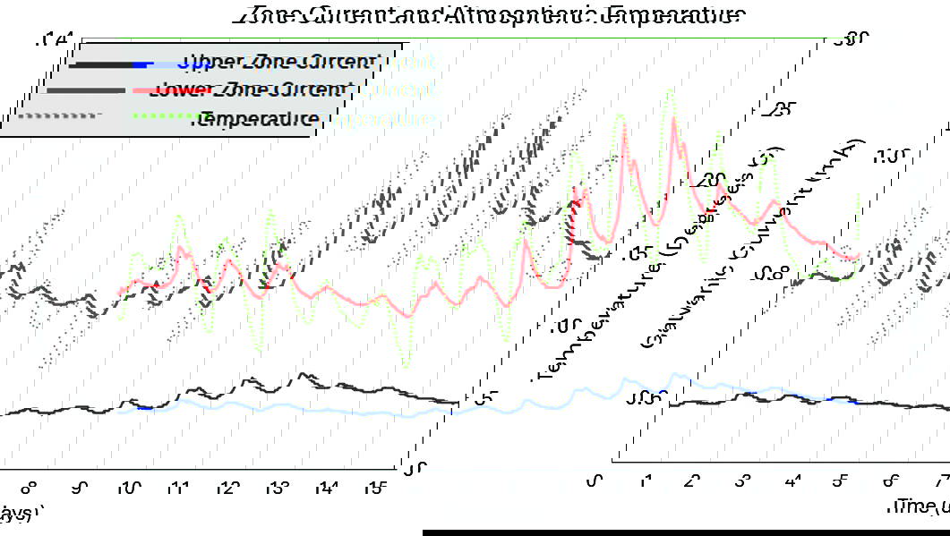
After flooding and rainfall, we can see that not only does the current increase due to the moisture ingress, but it also falls slowly as the moisture evaporates, leading to increased protection during the entire period of increased risk. Furthermore, some of the peaks in current seen during periods of increased moisture are larger than

the initial anode current, indicating that the current output is not being primarily driven by a build up of corrosion products or a depletion in activator for these systems but a reaction to the environment and the corrosion risk.

Testing he Predictive Power of The Half-Life ‘Ageing Factor’

In order to test the predictive power of the model, we must choose a null hypothesis against which it will be compared. The simplest null hypothesis would be that the median current the system was producing between 8 and 9 years, the last year of the data set utilised by the authors, stays constant. This appears to be a fair null hypothesis to test their predicted values against, as one predicts a decrease and the other predicts no decrease in current.

The authors published a half-life ‘ageing factor’ of 2.9 years, where the current halves every 2.9 year period. Here we have plotted the predicted values for each hypothesis against the data collected from the site during the period from year 8 to year 17, approximately 3 ageing factors or an expectation that the current, if the model is correct, will fall by more than 87.5%. A log current graph was chosen to transcribe the half-life model data into a straight line in a similar fashion to that employed by Sergi in
his work.

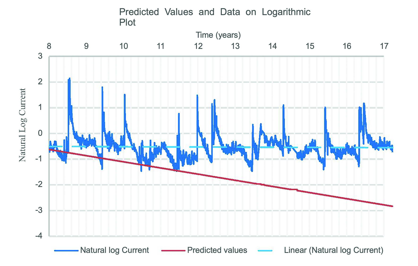
As can clearly be seen, the values predicted by the ‘ageing factor’ model (red) diverge from those measured on site over time, whereas the constant current model fits the data much more closely. This becomes evident when the mean squared error (MSE) of each predicted data set is measured; with the half-life hypothesis having an MSE of 0.237 mA2 and the MSE of a simple constant value
model being 0.0135 mA2, an order of magnitude smaller.

The error is likely due to a misunderstanding of how these anodes will behave differently over time due to their activation chemistry and presuming that the same methodology should be employed without testing other hypotheses, leading to the authors choosing to fit the same exponential decay that fit their own data. A simple change in their methodology to presume an exponential decay overlaying a more stable pattern can lead to a much better fit in the data and a lower MSE over the previously available data.

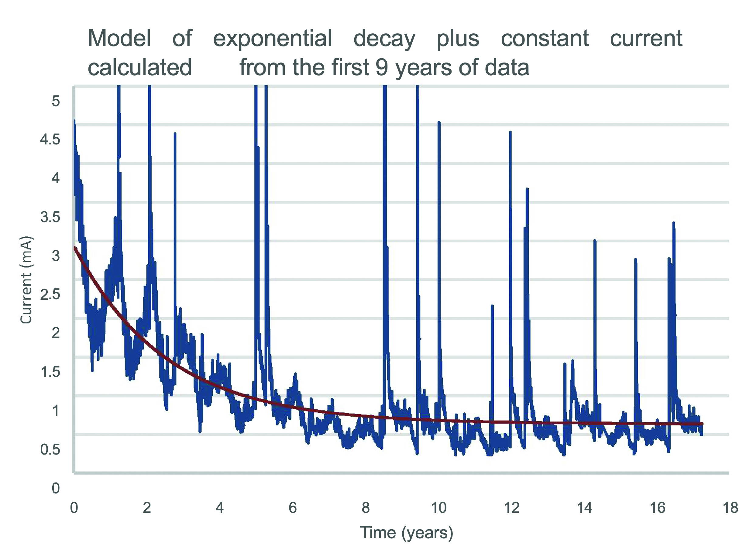
Below is an empirical model presuming a decay plus a constant current calculated using the first 9 years of data only. It should be noted that this is not a lifetime predictive model for these anodes, which will depend on many factors, as the anodes will not continue protecting the steel indefinitely and it is expected that when the volume of the anodes reduces beyond a threshold the ratio of zinc to steel surface areas will be insufficient to pass the same current. This fact in included in the design calculations of these anode systems. This is also not an endorsement of current being used as a benchmark for anode performance. However, as around 7% of the anodes on this site have currently been consumed, in the lifetime provided for this system it is unlikely to reach this threshold and this basic model may suffice, depending on environmental conditions. Therefore, over this limited time period, a relatively stable current may be used as changes in surface areas are relatively slow due to the anode geometry chosen by CPT and the activator should continue to keep the zinc active. An initial period of higher current due to the resistivity drop from the curing of the putty is also included in this limited model.

We believe that much of the error in the predicted value of the ageing term is due to the presumption that the overall behaviour would be similar. However, the difference in the activators used to keep the anodes active may lead to differing behaviour giving precast anodes an exponential decay of current to zero. This depletion in their activator, may lead to the amount of protection being in a large part dependent not on the amount of zinc but rather on the amount of activator utilised. Activators such as lithium hydroxide are consumed, may be leached away from the anodes, and carbonate after manufacture. Anodes activated in similar ways to PatchGuardTM and DuoGuardTM are likely to age very differently, as the availability of activator will not deplete in the same fashion and are therefore unlikely to show the same ageing characteristics. This can be seen clearly by calculating their hypothetical ageing constant using the data from years 8-17 using the same method as Sergi et al. Here we calculate the ageing constant over which the current is halved to be over 36,000 years. This is plainly absurd, as the zinc will be completely depleted after around 100-250 years. The underlying ageing of CPT anodes is therefore very unlikely to be exponential in nature.

Conclusions

It is clear from this data that the major factor driving the current output of CPT’s discrete anodes, is changes in the resistivity of the environment. After 17 years, the current was still responding strongly to changes in moisture, producing currents in excess of the median galvanic current from the first year of installation when moisture ingress reduces the resistivity of the environment. Precast anodes, such as the type used in the creation of the half-life model, may also be limited by a second factor, the depletion of their activator. This is concerning as these anode types are very popular worldwide and are often sold based on a mass of zinc, when, without sufficient activator, that mass of zinc will not be fully utilised. With lithium hydroxide as an activator, the mass of the activator would likely need to be much greater than the mass of zinc. It is likely, therefore, that only a portion of these anodes will be sufficiently activated before the current declines substantially.

Due to the depletion of activator, some form of ageing term may well apply to VCT style products as stated by their authors. However, due to this hypothesis failing to accurately predict the behaviour of other anode systems, it should be avoided in all specification documents as it may be unique to a certain set of products. It is important to ensure that clients are getting the same level of protection from anodes sold as equivalents in the market.

References

[1] G. Sergi, G. Seneviratne, D. Simpson, Monitoring results of galvanic anodes in steel reinforced concrete over 20 years, Construction and Building Materials, Volume 269, 2021, 121309, ISSN 0950- 618, https://doi.org/10.1016/j.conbuildmat.2020.121309.

[2] G. Sergi, Galvanic Corrosion Control of Reinforced Concrete: Lessons Learnt from 20 Years of Site Trials, ICorr presentation, Aberdeen, 30/03/2021, https://www.icorr.org/wp- content/uploads/2021/06/2021-03-30-ICorr-Aberdeen-Event-ICorr-Aberdeen-Presentation-30-03-21- Dr-George-Sergi-Vector-Corrosion.pdf 2021.

[3] G. Sergi, G. Seneviratne, D. Simpson, Monitoring results of galvanic anodes in steel reinforced concrete over 20 years, Construction & Building Materials, 269, 121309 2021.

[4] D. Whitmore, G. Sergi, Long-term monitoring provides data required to predict performance and perform intelligent design of galvanic corrosion control systems for reinforced concrete structures, Corrosion 2021, AMPP, Paper No. 16792, 2021.

[5] D. Whitmore, Design Considerations for Galvanic Anodes, ICRI webinar, December 2022.

6] G. Sergi, Life extension of existing steel reinforced structures by simple cathodic protection techniques for sustainable durability, Life-Cycle of Structures and Infrastructure Systems – Biondini & Frangopol (Eds), ISBN 978-1-003-32302-0 2023.

[7] G. Sergi, P. McCloskey, D. Simpson, Long-term performance of galvanic anodes for steel reinforced concrete, 3rd Conference & Expo Genoa 2024, AMPP Italy,https://www.vector- corrosion.com/assets/page_renderer/Sergi_George-Extended_Abstract.pdf, 2024.

[8] L. Bertolini, B. Elsener, P. Pedeferri, & R. Polder, Corrosion of Steel in Concrete: Prevention,Diagnosis, Repair. Corrosion of Steel in Concrete: Prevention, Diagnosis, Repair, 1–392. 2005 https://doi.org/10.1002/3527603379.

[9] ISO BS EN 12696:2022.

[10] G. K. Glass, A. M. Hassanein, N. R. Buenfeld, Monitoring the passivation of steel in concrete induced by cathodic protection, Corrosion Science, Vol. 39, No. 8, pp. 1451-1458, 1997.

[11] C. Stone, G. K. Glass, Assessment Criteria For The Electrochemical Protection Of Steel, Australasian Corrosion Association Conference, Cairns, November 2024.

[12] Standard Test Method for Corrosion Potentials of Uncoated Reinforcing Steel in Concrete, ASTM C876 22b, October 2022[11] National Highways 5700 Series.

[13] C. Christodoulou, C Goodier, S. A. Austin. Site performance of galvanic anodes in concrete repairs. Concrete Solutions-Proceedings of Concrete Solutions, 5th International Conference on Concrete Repair 2014 Aug 18 (pp. 167-172). 2014.

[14] Corrosion of steel in concrete: investigation and assessment, BRE Digest 444, 2000, ISBN 860813615.

[15] Electrochemical tests for reinforcement corrosion, Concrete Society Technical Report 60, 2024.

[16] G. K. Glass, Statement to the Cathodic Protection Association, SCA technical Meeting, March2023.

[17] D. Bewley, High-power, low-maintenance, hybrid corrosion protection, Bridge construction and repair, Concrete, Oct 2016, pp. 25-27 2016.

[18] D. Bewley, C. Stone, Long-term monitoring of innovative corrosion control system yields fascinating results, Concrete, Volume 57, Issue 5 June 2023.

Editor’s Note

This Journal provides a platform to all to present their investigations and research. It is not the intention to endorse particular products and readers must satisfy themselves in regard to their applicability and their particular needs.

200 Years On: Sir Humphry Davy and Cathodic Protection

200 Years On: Sir Humphry Davy and Cathodic Protection

Meet The Authors

Dr Bruce Ackland obtained a Bachelor of Science with Honours in Physics in 1979 and a Doctor of Philosophy in 1984 from Monash University, in the Department of Materials Engineering. Bruce has worked in the corrosion and cathodic protection industry since 1982, forming Bruce Ackland and Associates in 1985. Cathodic protection projects have involved work throughout Australia, New Zealand, Asia, SE Asia, the Middle East, North Africa and the USA. Bruce maintains an active role as a member and chairman in Australian Standards committees, participates in relevant ISO standards working groups, is the current chairman of the Australian Electrolysis Committee and is an accredited ACA Corrosion Technologist.

Dr Kathryn Dylejko is a corrosion engineer based in Australia at the Defence Science and Technology Group, specialising in minimising and controlling corrosion on Navy platforms. With roots as a mechanical engineer in armoured vehicles since 2006, she transitioned to corrosion 12 years ago, leveraging computational modelling to optimise cathodic protection systems for Navy vessels. Kate’s expertise spans various facets of corrosion, with a keen focus on cathodic protection systems for maritime platforms. Her research includes electrochemical studies on calcareous deposits and corrosion potential monitoring across Navy vessels and wharves. Actively contributing to the Victorian branch of the Australasian Corrosion Association, Kate recently achieved certification as an AMPP CP2 Cathodic Protection Technician, reinforcing her commitment to advancing the practice of corrosion control technologies.

Dr Markus Büchler FICorr, is Director of the Swiss Society for Corrosion Protection, President of the European Committee for the Study of Corrosion and Protection of Pipes and Pipelines Systems (CEOCOR), and convenor of ISO TC 156 WG10 on cathodic protection of buried and immersed metallic structures.


Introduction

The year 2024 marks the 200th anniversary of the first two of three remarkable papers [1-3] by Sir Humphry Davy describing the earliest scientific investigations into what we now call cathodic protection (CP). Although the word “cathode” was not in use until proposed by Michael Faraday in 1834 [4], this paper will keep using the modern abbreviation “CP” for convenience. Similarly, Faraday also proposed using the word “anode” in his 1834 paper and we will call the anodic metals used by Davy as anodes, rather than “protectors”. 

Davy presented three seminal papers to the Royal Society in London, beginning with his first on January 22, 1824 [1] giving the scientific reasons, background and laboratory research results for the application of CP to prevent corrosion of copper sheeting on timber ships in seawater. His second paper describing additional experiments and observations for copper sheeting on vessels in Chatham and Portsmouth Navy dockyards was presented on June 17, 1824 [2] and his third paper detailing full scale research and results for ships on the high seas was read on June 9, 1825 [3].

There was controversy then, as there is now, about some aspects of Davy’s work  [5, 6]. This paper discusses some of these issues and demonstrates that Davy was well aware of any shortcomings but importantly, he also suggested possible solutions to overcome the occasional problem of an increase in fouling of the copper sheet under specific circumstances [3, 7]. Notably, the application worked unambiguously to prevent corrosion of the copper in all cases, with fouling only occurring on some vessels and Davy was in the process of understanding the differences in operational circumstances. It will be shown that it was primarily a loss in funding and a wish by the British Admiralty (after pressure from some ship’s captains and the media) for quick solutions that cut short further investigatory work after just two years (i.e. 1823 to 1825). It was left to future scientists and engineers to show how CP could be used effectively and efficiently to protect any metal or alloy immersed in an electrolyte, including even reinforced concrete [8]. When reviewing his work, it must be seen in the context of the scientific understanding of electrochemical processes at the time. For instance, Davy was able to formulate the principles and application of CP decades before the electron was discovered by J.J. Thomson in 1897 and long before chemical and electrochemical reactions were written in the format used today. Judging his discoveries against modern principles is unfair at best and anyway, he was spot-on about plenty of technical points, as will be seen.

Previous Discoveries Leading to Davy’s Understanding of Electrochemical Processes and “Cathodic Protection”

Humphry Davy quickly adopted and contributed to the electrochemical technology developed by luminaries such as Luigi Galvani [9],  Alessandro Volta [10], Nicholson and Carlisle [11] and others. An example of the terrific electrical power he was able to produce can be seen in Figure 1 which shows the battery banks below a lecture theatre where he was demonstrating electric arc lighting. The portrait of Davy in Figure 2 includes a typical Voltaic pile (typically consisting of alternating stacks of brine-soaked cards sandwiched between pieces of copper and zinc or other combinations of dissimilar metals), a common feature in portraits of electrochemical scientists.

This background placed Davy in a perfect position to investigate a costly corrosion issue for the British Navy. In 1822, Davy was first approached by the British Navy Board to provide advice regarding the corrosion of copper sheeting on the Royal Navy’s timber ships [5]. The copper sheeting was effective at protecting the ships’ timber from worms and preventing the growth of “weeds” which otherwise had the effect of slowing the ships movement through the water. Davy read the board’s letter to the Council of the Royal Society of which Davy was President. The Council formed a committee (with Davy as President) to investigate the matter and decided to test copper specimens supplied by the Navy. Davy eventually dispensed with the committee and began working personally on the problem in 1823, reported directly to the Admiralty on 17th January 1824 and then read a groundbreaking paper to the Royal Society on 22th January 1824.

Davy’s Paper of January 22nd, 1824

This, Davy’s first paper on CP, proves the ability of CP to prevent corrosion. There may well be other consequences, but the beneficial effect upon corrosion was unambiguously proven and is not in dispute.

Let’s look at some of the key issues raised in this first paper:

Davy, along with his assistant Michael Faraday, proved incorrect the general supposition at the time that the “rapid decay” (i.e. corrosion) of copper was due to impurities, surmising that “pure” copper was acted upon more rapidly than the specimens which contained alloy (although the type of alloying was not provided) and that “changes” (corrosion) in various specimens of ships copper collected by the Navy Board “… must have depended upon other causes than the absolute quality of the metal”. The quality of the metal is important but other factors were also believed by Davy to play a critical role including “temperature, the relative saltness (sic.) of the sea, and perhaps the rapidity of the motion of the ship; circumstances in relation to which I am about to make decisive experiments” [2].

Davy described “the nature of chemical changes taking place in the constituents of sea water by the agency of copper” and especially the importance of oxygen in the process.

Davy repeats his hypothesis from 1807 [12] (read 20 November 1806) “that chemical and electrical changes may be identical”; a feature clarified and enumerated by his assistant Michael Faraday [4] several decades later with what is now popularly called Faraday’s Law of electrochemical equivalence [4]. Davy then describes how, by this hypothesis, “that chemical attractions may be exalted, modified or destroyed, by changes in the electrical states of bodies”. In other words, change the electrical state from its natural positive or negative state (i.e. change the potential, another word not yet in electrochemical use) and you will cause the chemistry to change. Davy then notes that it was the “application of this principle that, in 1807, I separated the bases of the alkalies from the oxygene with which they are combined and preserved them for examination; and decomposed other bodies formerly supposed to be simple”.

All of these past works by Davy led him “to the discovery which is the subject of this Paper”.

It is a testament to Davy’s scientific method that he supported his hypothesis by past research results, created an understanding of the processes involved and then went on to test it in the laboratory and with full scale trials, collecting and analysing the data for comparison with the predictions of the hypothesis.

Once he had established the basis of his hypothesis, he went on to suppose that if copper “could be rendered slightly negative, the corroding action of sea water upon it would be null; (i.e. polarise the copper negative) and whatever might be the differences of the kinds of copper sheeting and their electrical action upon each other (i.e. galvanic effects), still every effect of chemical action must be prevented, if the whole surface were rendered negative” He then astoundingly says “But how was this to be effected? I first thought of using a Voltaic battery; but this could be hardly applicable in practice”. So, Davy first thought of using an impressed current CP system! He could hardly know that future DC power supplies would make impressed current an easy and common means of cathodically polarising a structure. Davy then says “I next thought of the contact of zinc, tin, or iron”; i.e. galvanic anode CP.

Davy, assisted by “Mr Faraday” then conducted a series of experiments using these three metals to mitigate corrosion on copper. He then reports that although tin was initially effective, “it was found that the defensive action of the tin was injured, a coating of sub-muriate (chloride compound of tin) having formed, which preserved the tin from the action of the liquid”; the tin chloride deposits reduced the effectiveness of tin as an anode. “ With zinc or iron, whether malleable or cast, no such diminution of effect was produced”. Davy now knew for certain that he had effective anodes for the galvanic CP of copper.

Davy and Faraday then proceeded to conduct numerous experiments using zinc and iron in various shapes and sizes attached to copper, including small pieces “as large as a pea”, wires, nails, sheets connected directly by wires, filaments, soldering etc, and always with areas of zinc or iron much smaller than the copper being protected.

Near the end of the paper Davy notes “…. that small pieces of zinc, or which is much cheaper, of malleable or cast iron, placed in contact with the copper sheeting of ships, which is all in electrical connection, will entirely prevent its corrosion”. It is an important note by Davy that the iron anodes were much cheaper, and we will return to this issue when discussing the next two papers presented to the Royal Society.

Finally, Davy says that in future communications he might describe other applications that the principle can be used “to the preservation of iron, steel, tin, brass, and various useful metals”. He was definitely aware that
the principle is widely applicable to any metal or alloy, a feature we enjoy today [13].

Davy’s Paper of June 17th 1824, Additional Experiments and Observations

Davy reports the results of sheets of copper connected to zinc, malleable and cast iron for many weeks in Portsmouth Harbour. He notes that cast iron, which is the cheapest and most easily procured of the materials tested “is likewise most fitted for the protection of copper” and lasts longer than malleable iron or zinc. Davy later however, after further research, recommends a preference to use zinc anodes rather than iron [3].

Davy anticipated and observed “the deposition of alkaline substances” on the copper being “carbonated lime and carbonate and hydrate of magnesia”. Nicholson and Carlisle had discovered the decomposition of water using a voltaic pile [11] (described by Davy as a “capital fact” [7]) and included a description of “the separation of alkali on the negative plates of the apparatus”, hence Davy’s anticipation. These now familiar calcareous deposits of calcium carbonate and magnesium hydroxide are crucial to
the efficiency of CP systems in seawater. Davy was clearly aware of the increase in alkalinity at the cathode and acidification at the anode.
(Note: Even though the concept of pH and the quantification of acidity
and alkalinity was not formulated until 1909 [14], Davy talks extensively about the alkalinity and acidity produced during galvanic coupling of different metals).

Davy also understood and documented that when the calcareous deposit completely covered the copper sheets, it could result in “weeds” and “insects” collecting on them. Davy then considers the amounts of calcareous deposits generated by various quantities of anode material. He found that using zinc and iron anode to copper area ratios from 1/35 to 1/80, the copper became coated with calcareous deposits but “weeds” eventually adhered to the surface as well. He then reports that when the ratio was reduced to 1/150 “… the surface, though it has undergone a slight degree of solution, has remained perfectly clean; a circumstance of great importance as it points out the limits of protection; and makes the application of a very small quantity of the oxidable metal, more advantageous in fact than that of a larger one”. So, Davy here cautions about the excessive application of anodes for the specific protection of copper in seawater when fouling is unwanted and illustrated that fouling could also be mitigated if careful selection of the anode quantities was made for the specific circumstances in which they were used.

Davy’s Paper of June 9th 1825, Further Research

Davy’s full-scale trials were generally very successful, certainly he prevented the copper corrosion, and he makes the comment that the fouling was usually not an issue if the vessel is on the move. He notes that mooring stationary in harbour allows calcareous deposits to form more readily (surface pH will rise more than when in motion) and weeds etc can adhere. He also mentions the quality of the copper may be important and that the proportion of the anode: cathode area ratio affects deposits.

He observed that the marine growths are often initiated on the iron oxides deposited near the anodes (“protectors’’); he recommends here a preference to use zinc anodes rather than iron, “Zinc, in consequence of its forming little or no insoluble compound in brine or seawater, will be preferable to iron …”

Davy defends his work from page 341 onwards in his 1825 paper where he says “A false and entirely unfounded statement respecting this vessel (the 28-gun “Sammarang”) was published in most of the newspapers, that the bottom was covered in weeds and barnacles. I was present at Portsmouth soon after she was brought into dock: there was not the smallest weed or shell-fish upon the whole of the bottom from a few feet round the stern protectors to the lead on her bow.” He goes on to describe other instances of fouling and non-fouling when protected and at least attempts to understand the various circumstances.It appears that cast iron anodes were used in most of the field trials on ocean-going copper sheathed ships. For instance, Davy states in the Bakerian Lecture of 1826 (p. 420) [7], when discussing the field trials and operations “… in the only experiment in which zinc has been employed for this purpose in actual service, the ship returned … perfectly clean”. Davy wanted to conduct further experiments on ships in service, because the mitigation of corrosion was proven and fouling only occasional for reasons he thought could have been elucidated by further work.

It seems reasonable to expect the vessel captains, wanting the most from the protection system, to add iron anodes at possibly excessive rates since they were relatively cheap, easily procured and then complain that fouling was unacceptable. This is corroborated by Davy’s observation [3] when discussing several ships returned from the West Indies that “The proportion of protecting metal in all of them has been beyond what I have recommended, 1/90 to 1/70; yet two of them have been found perfectly clean, and with the copper untouched after voyages to Demarara; and another nearly in the same state, after two voyages to the same place. Two others have had their bottoms more or less covered with barnacles; but the preservation of the copper has been in all cases judged complete”. Davy was therefore not reluctant to report fouling on some ships but balanced this with positive reports. Clearly it was possible to obtain both corrosion protection and no fouling; it would just require continued methodical research (and with ship owners/captains installing the recommended quantities of anodes rather than excessive amounts).

On the issue of fouling, F. James’ otherwise excellent article on Davy [5] claims that “Davy does not seem to have appreciated the side effect, and he was certainly unable to overcome it”. This is incorrect on two points; Davy did appreciate the issue if one refers to the scientific articles as we have above where Davy addresses this specific issue and he was in the throes of trying to better establish the conditions in which corrosion mitigation and acceptable amounts of fouling could be achieved. Unfortunately, ongoing pressure finally led the Admiralty to issue orders to the Navy Board on 19 July 1825 to discontinue the project [5], thus ending further research just two years after first being initiated. The historian S. Ruston, in an essay discussing Davy as the philosopher [6], seems to draw heavily on James’ article where Ruston writes “Unfortunately, what had worked in the laboratory did not work at sea …”. This is incorrect since there was no disputing that the corrosion was fully mitigated; it worked perfectly well and was the original aim of the Admiralty’s directions, with only fouling being a troublesome and sometimes unacceptable side effect. On this Ruston goes on to write “…the electro-plating (sic.) had a chemical side effect, which stopped the poisonous copper salts from going into the sea and resulted in ships’ bottoms being fouled thus slowing them considerably”. Although Ruston mistakes electrochemical protection used by Davy as “electro-plating”, the essay ignores the actual scientific words of Davy within his papers to the Royal Society where, as discussed above, he understood the effect of calcareous deposits, the effect on fouling and the need to strike a practical balance between corrosion protection and fouling.

There was a lot riding on Davy’s work and competition from other inventors tied with the newspapers [5]. Plenty of “fake news” and “alternative truths” – not much has changed! If we study these works with our scientific, objective eyes we can establish a good understanding of the success or otherwise of Davy’s work. Davy makes so many great and insightful statements about his observations, many of which are equally valid today. Also don’t forget that he had the greatest assistant one could imagine in Michael Faraday in these works. The veracity of Davy’s publications is not in doubt, especially with Faraday on board.

Today’s Navy

The world’s navies to this day use cathodic protection on virtually every ship, submarine and marine vessel on the oceans and waterways across the globe to mitigate corrosion, both external to the hull and within internal water filled spaces [15-17]. Ships hulls are of course now predominantly coated steel, but Davy would surely have been pleased to know that zinc anodes are still used extensively as shown in Figure 3, using the same basic principles [17]. Impressed current systems are used for larger current demand applications on bigger vessels but even these are often supplemented with zinc anodes around high current demand areas and shielded locations such as sea chests, ballast tanks, propellers or shafts. Aluminium alloy anodes also provide excellent, cost-effective performance in seawater, but zinc is especially versatile when vessels experience waters of varying salinity such as estuaries and harbours with freshwater inflow.

Conclusions

Although the intent of this paper is to focus on Davy’s work, it is important to note that in the decades and now centuries following Davy’s work extraordinary advances were made in the understanding of the science that underpins CP [13, 18, 19], amongst other fields of science and engineering, this included:

•Michael Faraday’s discovery and experimental proof about the electrochemical equivalence between electric current and corrosion already mentioned.

•Josiah Gibbs’ development of the thermodynamics that lets us determine whether an electrochemical reaction can occur.

•Julius Tafel’s investigations and descriptions during the 1890’s and early 1900’s about how changes in the metal potential can regulate the anodic and cathodic reaction rates and

•Walther Nernst who showed how the potential of a metal could be calculated if the concentrations of reactants and products were known and in doing so, the stability of chemical species could be predicted if the potential and pH were known.

•Marcel Pourbaix summarised all of these features into his first beautiful Pourbaix diagrams [20, 21].

•Mears and Brown [22] also provided a clear kinetic description of CP in 1938 that is still valid today.

•R. J. Kuhn [23, 24] first suggested the earliest criterion for CP of polarising to -0.85 VCSE or more negative, which was shown to be suitable for steel, not only in seawater [25] but also in soils [26].

The increase in pH at the metal surface [27] and the subsequent development of passive oxide films during cathodic polarisation and their role in mitigating corrosion for steel, when considering both the kinetics and thermodynamics, is now well established for iron and steel alloys [28-30] and our deeper understanding continues to evolve, as good science always does.

Role of Calcareous Deposits

•It was recognised very early on [31] that the primary protective action of the calcareous deposits is to; (i) act as a barrier to oxygen or other depolarisers, (ii) increase the internal resistance of the local corrosion cells and (iii) increase the pH of the water film in contact with the metal surface above that of normal seawater. The benefits to marine cathodic protection systems are now well known, particularly in reducing the current density requirement for corrosion mitigation [31-35], a feature reflected in various industry standards for marine structures [36-38].

•The formation of calcareous deposits anticipated and observed by Davy is also still of special interest today and the circumstances of their formation continue to be investigated [17, 39]. R. J. Kuhn [24] also noted the formation of calcareous deposits that varied from “… practically nothing in neutral areas to an inch in thickness in heavily drained areas”, and hence in the degree of the protective or beneficial efficiency.

•The calcareous deposits formed by CP can also have detrimental effects such as accelerated bearing wear in water-lubricated propeller shafts and seizing of hull valves due to clogging [17], or in non-seawater applications such as limiting heat transfer of pumps causing overheating. Means of avoiding these adverse effects continue to be investigated [17], along with understanding the effects of CP upon biofouling [40].

Davy achieved remarkable success even though after 200 years, issues with the protection of metals and alloys using CP are still the subject of ongoing research and refinement. The future remains bright, with vigorous research continuing worldwide into CP, advancing the science and range of applications to an ever-widening array of structures. Science never sleeps and no doubt each new generation of scientists and engineers will, bit by bit, keep adding to our knowledge and advance Davy’s legacy.

References

1. Davy, H. (1824) OVI. On the Corrosion of Copper Sheeting by Sea Water, and on Methods of Preventing This Effect; and on Their Application to Ships of War and Other Ships. Philosophical Transactions of the Royal Society of London 114 January 22, 1824 151-158

2. Davy, H. (1824) XII. Additional Experiments and Observations on the Application of Electrical Combinations to the Preservation of the Copper Sheathing of Ships, and to Other Purposes. Philosophical Transactions of the Royal Society of London 114 June 17, 1824 242-246

3. Davy, H. (1825) XV. Further Researches on the Preservation of Metals by Electrochemical Means. Philosophical Transactions of the Royal Society of London 115 June 9, 1825 328-346

4. Faraday, M. (1834) On Electro-chemical Decomposition, continued (part of Experimental Researches in Electricity – Seventh Series). Philisophical Transactions of the Royal Society of London 124 77-122

5. James, F. A. J. L. (1992) Davy in the dockyard: Humphry Davy, The Royal Society and the electrochemical protection of the copper sheeting of His Majesty’s ships in the mid 1820s. Physis 29 205-225

6. Ruston, S. (2019) Humphry Davy: Analogy, Priority and the “true philosopher”. AMBIX 66 (2-3, May-August) 121-139

7. Davy, H. (1826) The Bakerian Lecture. On the relations of electrical and chemical changes. Philosophical Transactions of the Royal Society of London 116 383-422

8. Cherry, B. and Green, W. (2021) Corrosion and Protection of Reinforced Concrete, CRC Press

9. Galvani, L. (1791) De Viribus Electricitatis in Motu Musculari Commentarius (A Commentary on the Powers of Electricity in Muscular Motion). De bononiensi scientiarum et atrium instuto atque academia Commentarii 7 363-418

10. Volta, A. (1800) On the Electricity Excited by the Mere Contact of Conducting Substances of Different Kinds. Philosophical Transactions of the Royal Society of London 90 403-430

11. Nicholson, W. (1800) Account of the Electrical or Galvanic Apparatus of Sig. Alex.Volta and Experiments performed with the same. Nicholson’s Journal of Natural Philosophy, Chemistry and the Arts 4 (July) 179-191

12. Davy, H. (1807) The Bakerian Lecture, on some chemical agencies of electricity. Philisophical Transactions of the Royal Society of London 97 1-56

13. Ackland, B. G. (2012) Cathodic Protection – It Never Sleeps. In: Corrosion and Prevention 2012, Plenary no. 4, Melbourne: 11-14 November 2012, Australasian Corrosion Association

14. Sörensen, S. P. L. (1909) Enzymstudien. II. Mitteilung. Über die Messung und die Bedeutung der Wasserstoffionenkoncentration bei enzymatischen Prozessen [Enzyme studies. 2nd Report. On the measurement and the importance of hydrogen ion concentration during enzymatic processes]. Biochemische Zeitschrift (in German) 21 131-304

15. Morgan, J. (1987) Cathodic Protection. Second ed, National Association of Corrosion Engineers, Houston, Texas

16. von Baeckmann, W., Schwenk, W. and Prinz, W. (1997) Handbook of Cathodic Corrosion Protection, Gulf Professional Publishing

17. Dylejko, K., Neil, W. (2024) Plenary Lecture – Cathodic Protection and its Implications for Vessels in the Royal Australian Navy. In: Australasian Corrosion Association Conference 2024, Cairns, Australia

18. Ackland, B. G. (2005) P.F. Thomson Memorial Lecture – Cathodic Protection – Black Box Technology? In: Corrosion and Prevention 2005, paper no. 4, Brisbane, Australia, Australasian Corrosion Association

19. Martinelli-Orlando, F., Mundra, S. and Angst, U. M. (2024) Cathodic protection mechanism of iron and steel in porous media. Communications Materials 5 (1) 2024/02/16 15

20. Pourbaix, M. (1945) Thermodynamique des solutions aqueuses diluées. Représentation graphique du rôle du pH et du potentiel. Delft

21. Pourbaix, M. (1974) Atlas of Electrochemical Equilibria in Aqueous Solutions, National Association of Corrosion Engineers

22. Mears, R. B. and Brown, R. H. (1938) A Theory of Cathodic Protection. Transactions of The Electrochemical Society 74 (1) January 1, 1938 519-531

23. Kuhn, R. J. (1933) Cathodic Protection of Underground Pipe Lines from Soil Corrosion. API Proceedings 14 (Section 4) 153-167

24. Kuhn, R. J. (1928) Galvanic Current on Cast Iron Pipes – Their Causes and Effects – Methods of Measuring and Means of Prevention. In: Soil Corrosion Conference, Washington: December 10, Bureau of Standards

25. Schwerdtfeger, W. J. (1958) Current and Potential Relations for the Cathodic Protection of Steel in Salt Water. Journal of Research of the National Bureau of Standards 60 (3) March 1958 153-159

26. Schwerdtfeger, W. J. and McDorman, O. N. (1951) Potential and Current Requirements for the Cathodic Protection of Steel in Soils. Journal of Research of the National Bureau of Standards 47 (2) August 1951 104-112

27. Kobayashi, T. (1974) Effect of Environmental Factors on the Protective Potential of Steel. In: Proceedings of the 5th International Congress on Metallic Corrosion, Houston, Texas, NACE

28. Angst, U., et al. (2016) Cathodic Protection of Soil Buried Steel Pipelines – A Critical Discussion of Protection Criteria and Threshold Values. Werkstoffe und Korrosion 67 (11) 1135-1142

29. Angst, U. (2019) A Critical Review of the Science and Engineering of Cathodic Protection of Steel in Soil and Concrete. Corrosion 75 (12) 1420-1433

30. Freiman, L. I., Kuznetsova, E.G. (2001) Model Investigation of the Peculiarities of the Corrosion and Cathodic Protection of Steel in the Insulation Defects on Underground Steel Pipelines. Protection of Metals 37 (5) 484-490

31. Humble, R. A. (1948) Cathodic Protection of Steel in Sea Water With Magnesium Anodes. Corrosion 4 (July) 358-370

32. Wolfson, S. L. and Hartt, W. H. (1981) An Initial Investigation of Calcareous Depsoits Upon Cathodic Steel Surfaces in Sea Water. Corrosion 37 (2) 70-76

33. Ryan, L. T. (1954) Cathodic protection of steel-piled wharves. Journal of the Institute of Engineers, Australia 26 (7) 160-168

34. Humble, R. A. (1949) The Cathodic Protection of Steel Piling in Sea Water. Corrosion 5 (September) 292-302

35. Hartt, W. H., Culberson, C. H. and Smith, S. W. (1984) Calcareous Deposits on Metal Surfaces in Seawater – A Critical Review. Corrosion 40 (11) 609-618

36. ISO 15589-2 Oil and gas industries including lower carbon energy — Cathodic protection of pipeline transportation systems, Part 2: Offshore pipelines.  (2024).

37. DNV-RP-B401 Cathodic protection design.  (2021).

38. AS 2832.3 Cathodic Protection of Metals Part 3: Fixed Immersed Structures.  (2005).

39. Carre, C., Zanibellato, A., Jeannin, M., Sabot, R., Gunkel-Grillon. & Serres, A. (2020) Electrochemical calcareous deposition in seawater: A review. Environmental Chemistry Letters 18 1193-1208

40. Vuong, P., McKinley, A. & Kaur, P. (2023) Understanding biofouling and contaminant accretion on submerged marine structures. npj Materials Degradation 7 Article 50, https://doi.org/10.1038/s41529-023-00370-5

Fellow’s Corner

Fellow’s Corner

This series of articles is intended to highlight industry-wide engineering experience, guidance and focussed advice to practising technologists. It is written by ICorr Fellows  who have made significant contributions to the field of Corrosion Management.

B S Wyatt is an ICorr Past President, a member of the CP Governing Board (CPGB) and CEOCOR Immediate Past President. Brian is an independent Consulting Corrosion Engineer, a CP specialist in applications for steel in soils, waters and concrete. Experienced in design, performance assessment, detailed survey techniques and remedial work for:

• Onshore buried and offshore pipelines
• Offshore new build and retrofit CP for oil, gas and renewables structures
• Internal and external surfaces
• Coastal and port/harbour structures
• Steel in concrete for bridges, tunnels and buildings.

Brian is an expert witness in multiple sectors of CP, he has carried out technical consulting and project management of large and complex CP systems. He is a UK Nominated Expert by BSI for CEN/TC219 and ISO TC156/WG10. He is active in the ICorr Training, Examination and Certification of CP personnel in accordance with BS EN ISO 15257. Brian has competence Certification to ISO 15257 Level 4 in all 4 Sectors: Buried, Steel in Concrete, Marine and Internals and Certification to Level 5.

The Role of an Expert Witness

Introduction

I have been requested by the Editor to submit a paper on the role of an expert witness. For reasons I will explain below, this is quite a difficult task, but I will do my best within the necessary confidentiality of cases in which I have been appointed to this role.

There are several other Fellows of ICorr working as expert witnesses. Some, like me, only occasionally undertake such work, others have chosen this activity as a major part of their fee earning activities. One is resident in and very active in the USA.

I explain below, how I assess approaches from legal teams and determine if I think I am suitable for, and if I am prepared to act as an expert, in the case in which they are involved.

For those readers who have not experienced technical or construction disputes, and whose exposure to the actions of expert witnesses may be limited to newspaper reports of criticisms of expert witnesses, or the reported inadequate understanding of expert witness testimony by the courts, for example in UK medical negligence cases, or to fictional US cases in criminal cases, please be ready to be disabused.

General Rules

Firstly, the rules for expert witnesses are quite different in the UK and the USA. I have taken guidance in the summary below from the Global Arbitration Review1 and from Bond Salon2.

England and Wales have established the Civil Procedure Rules: Rules and Directions, Part 35 (CPR Part 35)3, which set out the requirements for expert evidence, specifically requiring that an expert witness has an overriding duty to the court to be independent and impartial. As a result, ‘experts should constantly remind themselves through the litigation process that they are not part of the Claimant’s or Defendant’s “team” with their role being the securing and maximising, or avoiding or minimising, a claim for damages. Although experts always owe a duty to exercise reasonable skill and care to those instructing them, and to comply with any relevant professional code, as CPR 35.3 expressly states, the experts have at all times, an overriding duty to help the court on matters within their expertise. That they have a particular expertise and the court and parties do not (save in some professional negligence claims) mean that significant reliance may be placed on their analysis, which must be objective and non-partisan if a just outcome is to be achieved in the litigation.4

From Ref 1 ‘The UK judiciary has made criticisms of expert evidence in, for example, ICI v. Merit,[15] Riva v. Fosters,[16] Energy Solutions v. NDA[17] and Russell and Anor v. Stone,[18] which highlighted that a ‘hired gun’ who pretends to be independent is of little help to a tribunal and may damage the position of the instructing party. It may cause the parties to incur higher expenses in the whole proceedings, prevent any settlements or render the expert evidence of little assistance to the tribunal. An expert must maintain objectivity and independence. The English courts have given many judgments regarding the bias of experts; for instance, in Jones v. Kaney,[19] the Supreme Court of the United Kingdom removed the immunity of an expert witness from lawsuits for negligence.’

Expert witness reports are required to contain a ‘statement of truth’ which would typically be in the following form:

‘I confirm that I have made clear which facts and matters referred to in this report are within my own knowledge and which are not. Those that are within my own knowledge I confirm to be true.

The opinions I have expressed represent my true and complete professional opinions on the matters to which they refer.

I understand that proceedings for contempt of court may be brought against anyone who makes, or causes to be made, a false statement in a document verified by a statement of truth without an honest belief in its truth.’

In one case in which I was involved, I was asked to attend chambers of the leading barrister who would be putting the case for the party who had appointed me. One of the expert witnesses for the other party had made claims that I considered to be spurious and that were directly contradicted by a published document that the expert had previously written; I had identified this in my opinion report. The barrister [many of whom can be quite robust] described the expert as a ‘man of straw’ and said that he would ‘enjoy picking the wings off this fly’. The case was settled before the hearing.

In the United States, Federal Rules of Evidence (US FRE) Article VII sets out the requirements governing the rules for opinion and expert testimony, which are less prescriptive. The conduct of expert witnesses, and their overriding duty to serve and assist the court, is not established under the US FRE. I am advised by my expert fellow colleague that there are differing rules in different states.

Corrosion expert witnesses in the USA and elsewhere, must be experienced and have specialized knowledge or skills to offer unbiased opinions to help attorneys, judges, mediators and juries understand complex corrosion issues.  The Daubert Standard5  is now the law in federal court and in other courts over half of the states.   Related to Daubert, attorneys may question expert witnesses if they are knowledgeable in the Scientific Principle6 7, which is intended to eliminate bias.

In the USA, a corrosion expert – before testifying – must stipulate that their scientific or engineering knowledge will assist the court or tribunal understand the facts in issue.  These responsibilities should ensure that expert witnesses are able to play a crucial role in ensuring fair and informed decision making in legal cases.

In international disputes the contract terms will normally have defined the rules and jurisdiction under which any dispute will be subject to arbitration or settlement, if the latter, often by an expert tribunal. In all in which I have been involved the CPR Part 35.3 rules have been applied either formally as these rules by name or by direct copying of their requirements. In large international construction contracts, the parties may have agreed to use a particular form of arbitration to address any disputes; one such is prepared by the United Nations Commission on International Trade Law (UNCITRAL).

With all this being said, the reality is that once appointed, all the information related to the case that the expert requires to properly execute his or her work comes from the instructing party’s legal team, and it is normal for there to be meetings with the legal team and with the instructing party’s personnel who have information on the matters in dispute. Eventually, some of these personnel with intimate knowledge of the matters in dispute will present their own witness statements. During the process there will be a need for legal advice for the expert in respect of procedures for the hearings in court or before a tribunal. Draft expert reports may be commented on by the instructing party’s legal team and barrister(s); however, at no time should the expert be prepared to receive or act on instruction to change his or her expressed opinion. During a long preparation for a hearing there is a risk that a ‘team spirit’ is developed, particularly if there are multiple experts with interlocking expertise; hence the emphasis in Ref. 4 above: ‘Experts should constantly remind themselves through the litigation process that they are not part of the claimant’s or defendant’s “team”, with their role being the securing and maximising, or avoiding or minimising, a claim for damages.’

In all of the expert witness cases in which I have been involved, before tribunals or an arbitration expert, the evidence and the outcome, where it has become known to me, have been strictly confidential. The details remain so. Therefore, my description of the process is necessarily restricted. In cases that are heard in the Technology and Construction Courts  , the CPR Part 35 rules apply, however, the judgements are published.

In my experience a typical process has been:

1. The Initial Contact

A phone call or e-mail, out of the blue, often from a legal professional, but occasionally from a technical or scientific professional with expertise in a related or unrelated field, typically asking guarded

questions regarding expertise, availability and, very soon, regarding conflicts of interests.

This might proceed to the exchange of limited documents regarding the dispute and the parties, under a confidentiality agreement. It is at this point where, historically, I have sometimes declined to be involved, either because I am not comfortable acting for the ‘instructing party’, or I think from the limited information available the instructing party’s case is likely ill-founded or indefensible, or I consider that my expertise is not appropriate for the scope of the case. Where I can, I have pointed the enquirer towards people, often also Fellows of ICorr, who I think are either more competent than I am in that field or more likely to wish to work on the particular case.

If I am interested and available and the key issues are within my expertise and still under confidentiality agreements, there are exchanges of more technical details, sometimes preliminary timetables and suggested fees. It is at this stage, before any appointment that I detail, that I describe, I hope honestly and self-critically, my relevant technical strengths and weaknesses.

2. The Appointment

Typically, quite quickly, a draft engagement letter will be sent by the instructing legal team, detailing who they act for, who are the parties to the dispute, and the jurisdiction which will hear the details of the dispute by way of the claims and counter claims, which may be an Arbitration Board, Tribunal or a Court. The engagement letter may also detail other experts already appointed, providing other expertise [e.g., coating, testing, etc.], and it may outline in more detail the provisional timetable. The legal team will have obtained approval from the court or tribunal for the appointment of experts and their anticipated costs.

The engagement letter will require confidentiality and ‘legal privilege’; likely all documents to and from the expert will be marked ‘Privileged and Confidential – prepared for use in XYZ proceedings. It will require disclosure of any conflicts of interest [which will likely exclude the expert from the proceedings] and either directly or indirectly, compliance with the CPR Part 35 rules. In all such cases, the workload and the attention to detail required are abnormal. I have had multiple boxes of small print A5 files of evidence arrive by courier on a Friday evening with a requirement for initial comments the following Monday morning. Every word on the page of an expert witness report, or ppt. presentation to be used in evidence should be 100% accurate and impossible to be misinterpreted.

In one of the largest cases in which I was involved, I gave evidence for a day and a half and ‘suffered interrogation’ from the most aggressive barrister I have ever met. My expert technical report, which I had worked on for many, many hours, was hardly addressed. I was advised afterwards that he could find nothing of substance in it to challenge, and his challenges were primarily of me and my expertise. Before this long tribunal hearing, I was grateful to have taken part in some expert training in how to deal with such questioning and how to react in front of the tribunal.

3. The Work Process

The overall Work scope typically falls into 4 stages:

• Outline and Scheduling

• Assessment

• Review and Final presentation

• Proceedings

Outline and Scheduling

Initially the expert will be presented with the claims and counter claims from the parties in the dispute, the claimant and the respondent.

At a relatively early stage in the process a draft timetable will be published advising when expert reports are to be submitted, if an ‘experts meeting’ is required, and when court or tribunal hearings are planned. At around the same time a list of experts will be exchanged between the claimant and respondent. This may result in an

assessment of particular areas of expertise being brought to bear on the evidence by one party and the need for the other party to strengthen the expert witness team in this area. It is critical at this time for any appointed experts to be realistic in respect of the limits of their expertise and experience. I have advised a legal team that a particular expert in the team for the other party had expertise beyond mine in what could be a relevant sector, and that the legal team should consider adding another expert in order to competently address matters within this sector.

Assessment

Then the real work begins, with a thorough review of all the available evidence, possibly requesting additional information if any is available, or suggesting additional testing in order to better inform if there is any ‘fault’ or to better determine the impact of any such fault on the required performance of the asset at the core of the dispute. All such requests and any additional data or site visits and their outcomes must be openly shared between all of the parties.

Depending upon the complexity of the dispute there may be many hundreds of relevant documents. Different legal firms have different methods of presenting these to experts, some largely in hard copy bound documents, some in well-constructed and easy to access electronic systems and some in less easy to use systems.

Review and Final presentation

I have been involved in a number of cases as an expert where I have been required to prepare power point presentations for the tribunal or arbitration board. The purpose is to present an accurate summary of the previously prepared expert opinion report which can be presented before the tribunal. Draft expert reports or opinions are presented, and questions can be submitted between claimant and respondent, in order to seek clarity.

It may also be required that experts appointed by both claimant and respondent meet, in what is termed an ‘experts meeting’ with the intention of determining what, if any, matters in dispute can be agreed between the experts, and thus to be removed from,  or closed off in, the later revisions of the expert opinion reports and the eventual proceedings. The intention is to simplify and reduce the costs of the process, whilst retaining the key issues in the dispute to be assessed by the court or tribunal without the distraction of matters that can be agreed. These meetings between experts are normally ‘without prejudice’ and the legal teams for the claimant and respondent may determine not to accept removing the agreed items from the dispute.

Proceedings

Experts should be prepared for the parties to a dispute to reach a compromise agreement in the weeks or even days before the planned court or tribunal hearing. This has happened to me in several cases.In one particularly complex overseas case I had been to the job site for some weeks, collecting more information and, in parallel, preparing the final version of my expert opinion report, along with a power point presentation to be used in the hearing. On the day before my planned time before the tribunal, for which I considered I was well prepared, I was phoned and told to go home; the matter had been settled. At the time I was disappointed, thinking that part of my work was incomplete; on reflection on this and other disputes settled before the planned court or tribunal hearing, the appropriate conclusion is that the expert has, to the best of his or her’s ability, clarified the matters in dispute for the parties and the court/tribunal in order to facilitate an agreed settlement. Job done.

Personal Experiences

Over the years I have been appointed as an expert in cases related to CP failures on sheet steel piles in seawater and saline infills, hot oil pipelines, to district heating schemes, to pipelines in swamps with disputed field joint coating quality, a buried pipeline with disputed field joint coating quality and disputed CP system adequacy, offshore wind farm monopile foundations, ship hull coatings and related CP performance and others. The Figures to the right are NOT from expert witness cases in which I have been appointed [due to confidentiality issues] but examples of some of the sectors in which I work.

External Corrosion on Buried Gas Transmission Pipeline:

The Thames Barrier London (not a dispute but a success where independent experts were assessing the corrosion protection performance)

A project on which I was involved for many hours alongside another Past President of ICorr, David Deacon. David was a respected coating expert, but not a believer in CP. He was persuaded of the efficacy of CP on this project, which was well designed by our mutual expert predecessors and we had the pleasure of assessing their success:

In my non-dispute related experience, often with colleagues, I have investigated and assisted in developing and executing remedies for failed corrosion protection schemes [CP, coatings and other related matters] or as independent technical expert(s) advising employers in complex CP related schemes being designed and executed by others. Much of the same rigour and obligations mandated to be applied in technical or construction dispute resolution outlined above are applicable to these activities. From my personal experience, expert witness work can be significantly disruptive to other professional activities and to personal life, but I have enjoyed the intellectual challenge of attempting to make the evidence to the court, or tribunal, complete, clear, detailed and as far as possible, difficult for a barrister whose role is to demolish my evidence or credibility to the benefit of his or her client, to misinterpret. In all of this, the evidence is not for the barristers, it is for the judge or tribunal panel and is intended to make what can be quite complex and subtle technical matters clear to all.

References

1. https://globalarbitrationreview.com/guide/the-guide-construction-arbitration-archived/fifth-edition/article/expert-evidence-in-construction-disputes-expert-witness-perspective .

2. https://www.bondsolon.com/expert-witness/expert-witness-training/

3. https://www.justice.gov.uk/courts/procedure-rules/civil/rules/part35

Quotation from a Bond Salon briefing note regarding a 2022 dispute.

4. https://www.bailii.org/ew/cases/EWHC/KB/2022/2648.html

5. https://www.law.cornell.edu/wex/daubert_standard.

6. https://legalclarity.org/what-is-an-example-of-the-frye-standard-in-court/

7. Scientific principles give foundation to definitive expert opinions evaluating hypotheses for causation and feasibility for extraordinary claims.

8. https://www.judiciary.uk/courts-and-tribunals/high-court/technology-and-construction-court/


CED – Join the New CED Committee

CED – Join the New CED Committee

We’re rebuilding – and we want you with us

The ICorr Corrosion Engineering Division (CED) is undergoing a major refresh – and we’re looking for passionate corrosion professionals across the UK to help shape our next chapter.

Whether you’re working in energy, infrastructure, materials, asset integrity or beyond – if you care about corrosion and want to share your knowledge, build your profile, and contribute to a growing technical community… we’d love to hear from you.

We’re establishing a new committee to align with our refreshed structure and strategy. This is an exciting opportunity to join a supportive, cross-sector group with a shared vision:

Our Vision: To champion corrosion engineering through connection, collaboration, and contribution – bringing professionals together to share practical insights, tackle emerging challenges, and influence industry best practice.

Who We’re Looking For?

We welcome expressions of interest from individuals who are:

• Based in the UK

•Working in or passionate about corrosion engineering and science

• Keen to contribute their ideas, experience and time

•Interested in building their network, shaping strategy, or supporting technical activities

Whether you’re early in your career or a senior specialist, there’s a place for you.

Committee Opportunities

We’re currently seeking:

Vice Chair (with possible progression to Chair)

Working Party Leads – guiding topic-based technical communities

Committee Members – supporting events, outreach, and growth

Working Parties – Lead or Get Involved

As part of our revitalised structure, we’re forming broad, strategic working parties designed to be more inclusive, collaborative, and aligned with industry challenges:

Each group will meet 2–3 times a year and contribute to events, discussions, and outputs.

What’s involved?

We’re a volunteer-led committee and aim to keep involvement flexible, rewarding, and well-supported. Typical contributions include:

• Bi-monthly online committee meetings (30–60 mins)

• Working Party involvement (2–3 short meetings per year)

• Helping shape or promote our events and outputs

• Supporting outreach, mentoring, or knowledge-sharing

Key Annual CED Events

ICorr CED One-Day Technical Conference

    (April – aligned with Corrosion Awareness Day)

Paul McIntyre Award Presentation & Celebration

Technical Webinar (November/December)

ICorr AGM Participation and Reporting

What’s Next for the CED?

Our priorities for 2025–2026

• Rebuild a diverse, cross-sector committee

• Launch working parties aligned to current challenges

• Enhance our online presence and resource hub

• Strengthen collaboration with the Corrosion Science Division

• Celebrate excellence through the Paul McIntyre Award

• Continue growing our flagship events and technical visibility

Interested in Joining?

If you’re motivated by collaboration, knowledge-sharing and professional growth – and want to help move corrosion engineering forward – we want to hear from you.

Get in touch: Danny Burkle, Chair, Corrosion Engineering Division, Email:  CEDchair@icorr.org

CEng Updates

New application are being processed and assessors are adjustinh to their new roles.  The website is being updated to provide the documentation and processes as per the ICorr direct licence.

Our much-valued assessors come from varied backgrounds to review and assess the applications from ICorr’s wide-ranging membership. These volunteers are contributing to ICorr to support our members to attain the registration status with the Engineering Council.

Anthony Setiadi: Anthony is a chartered engineer currently working for Wood Thilsted, an offshore renewable consultancy. He has more than 20 years in the industry covering various energy and infrastructure roles and studied materials science at the University of Sheffield. He works in materials selection, coating and cathodic protection. He is also supporting ICorr as vice president and has been leading the ICorr registration process for the past 3 years.

Greg Brown: Greg is a senior materials engineer at Mott MacDonald, and he is currently chair of the ICorr Northwest branch. He is highly experienced in destructive and non-destructive testing and is a chartered engineer. He has been part of the Registration committee for the past 2 years.

Jim Preston: Jim is Managing Director of Corrosion Prevention Limited. He has worked in the fields of structural concrete repair and cathodic protection for over 30 years, including 15 years working for contracting organisations and latterly 15 years as a consultant. He is a Chartered Engineer and a Fellow of ICorr. He is a certified Level 4 CP Specialist in accordance with ISO 15257.

Ashokan Gopal: Ashokan Gopal is an electrochemical engineer and an industry-recognised cathodic protection expert in the UK with over 18 years of experience in the field of corrosion mitigation and cathodic protection. He is a chartered engineer with a master’s in corrosion control engineering from the University of Manchester. He is currently the vice-chair for the London ICorr Branch and an active member of the ICorr CPGB, working closely with the industry’s best minds. He is a certified Level 4 CP Specialist in accordance with ISO 15257.

Emilya Abdullayeva: Emilya is a senior corrosion engineer in SLB with 20+ years of experience in corrosion engineering, integrity chemicals, and microbiological control across upstream oil and gas operations. She has a master’s degree in engineering oil and gas and a PhD in corrosion inhibitors and MIC control in the oil and gas industry. Chartered Chemist from the Royal Society of Chemistry and Chartered Engineer from ICorr.

Ibtesam Hasan: Ibtesam is a chartered metallurgy and materials engineer with over 20 years of experience in offshore oil and gas. He currently manages P&L for IMR operations for the Fugro Middle East office. He holds degrees in metallurgy and materials and a PgD in corrosion control engineering, complemented by NACE and API certifications.

Azri Aziz: Azri is a chartered engineer and currently works as a senior corrosion engineer at Aramco. He has 14 years of experience in corrosion engineering and integrity management within the oil and gas industry. He holds a degree in Materials Engineering and an MSc in Corrosion Control Engineering, complemented by professional certifications from the American Petroleum Institute (API) and AMPP. Azri has a strong track record of developing and implementing integrity management strategies, ensuring asset reliability and driving industry best practices in corrosion control in operating assets.

Lian Ling Beh: Lian is a chartered engineer and professional member of ICorr. She is a materials and corrosion engineer with nearly 20 years of experience in asset integrity and management in the North Sea. Currently supporting operations across BP’s NS assets, providing consultation to multidisciplinary teams, including pressure systems, pipelines, mechanical and rotating equipment, structural integrity and lifting equipment.

Olubayo Latinwo: Olubayo is an asset integrity specialist with over 20 years’ experience across international oil and gas assets. He earned his PhD in Engineering Materials in 2012. Olubayo is a professional member of ICorr, IOM3 and IAM. He is also a Chartered Scientist and Chartered Engineer with the Science and Engineering Council, respectively, and also has multiple qualifications with AMPP and API. He has been part of the Aberdeen Branch of the Institute of Corrosion for 6 years in various roles, including Vice Chair. He has also been a formal PAC assessor for the MICorr grade for over 4 years with the Institute of Corrosion.

Syed Umair Niaz: Syed is a Chartered Scientist and Chartered Engineer with nearly 15 years of experience, having a degree in mechanical engineering with a strong focus on corrosion management, coating selection, and welding integrity. He has authored numerous publications in these fields and currently works with EDF France, based in the UK, leveraging his expertise to drive innovation and excellence. He is also serving ICorr as a member of the Professional Assessment Committee (PAC) and an assessor for CEng registrations.