The Institute of Corrosion has developed a programme to assist Engineers and Technicians obtain their Chartered Status.
The Society of Environmental Engineers (SEE) in an agreement with the Institute of Corrosion, has been licensed by the Engineering Council to confer registration as a Chartered Engineer(CEng), Incorporated Engineer (IEng) or Engineering Technician (TechEng).The Engineering Council sets standards for competence and commitment to become registered as set out in the UK Standard for Professional Engineering Competence (UK-SPEC). The Institute of Corrosion has interpreted these standards and developed the professional competences required for registration.Chartered Engineer status demonstrates the achievement of a high-level education, the ability to practise the profession at a recognised level, and the maintenance and continued progression of engineering competencies.
The objectives of this programme are to support ICorr members to reach the required competency levels in the field of corrosion engineering to obtain Chartered Engineer status via a “Mentoring” approach to assess competency and advise development programmes to reach CEng.The benefits to Engineers and Technicians are, mentor guidance from an industry professional, competency assessment from a Chartered Engineer, a development programme via the competency matrix.Once a suitable mentor is appointed and the competency matrix completed a program is developed to assist the candidate towards the Chartered status goal. This could include suggested training, site visits, conference involvement or assistance in completion of the application and guidance for the PRI.
Who Should Apply? Engineers who have graduated and have completed 2 years in Industry, any member of ICorr who believes they are ready to progress to CEng, and mature engineerswho have the experience but lower academic qualifications.
More information can be found on the Institute of Corrosion Website, or you can contact ICorr HQ, or the Chartered
Status Team.
Rob Allan, Emre Karapinar, Malcolm Morris, Neil Wilds and Sarah Vasey, Sherwin-Williams Protective & Marine Coatings.
Glass Flake Epoxy (GFE) technology has been a main stay of the Oil &Gas (O&G) offshore market for many years, particularly for highly aggressive splash zone areas, despite other technologies for similar end uses having been investigated. This, consequently, resulted in the opportunity of assessing the performance of these materials in real life conditions and enabled coating suppliers to optimize their GFE formulations for wider end uses and longer service life times.
The versatility of glass flake epoxy technology allows it to be used not only for O&G offshore applications but for buried steel in O&G downstream applications, subsea pipelines and equipment, and even for bridges & highways where local authorities – such as Network Rail and Highways Agency in the UK – dictate the use of such a technology due to its superior anti-corrosion properties and longer service life times.
Use of glass flakes in combination with other functional pigments (for example, aluminium) or more advanced epoxy polymers (such as surface tolerant epoxies, epoxy novolacs, amine cured epoxy linings…etc) delivers effective long term protection of water, fuel, and chemical tanks, vessels and pipelines, as well as maintenance and repair of such steelwork whether it’s immersed or atmospheric.
Traditionally, glassflake coatings were based on relatively large particle size glass flake pigments (nominal width 0.4mm). These coatings typically required approx. 500µm to achieve a full film and an overall specification could be in excess of 1mm dry film thickness. However extensive research and development using significantly smaller glass flakes has enabled the production of formulations which could deliver equivalent performance at much lower film thickness, and with a vastly superior aesthetic appearance.
In this respect various tests have been conducted to understand the effect of glass flake pigmentation on the overall performance of epoxy coating systems. It is commonly accepted in the coatings industry that glass flake pigmentation increases barrier properties of the dry film and enhances mechanical properties, making it an ideal choice for immersed and buried steel. Table 1 clearly displays the benefit of using glass flake in a 500 microns thick dry epoxy film, which was loaded with 20% w/w glass flake at an average particle size of 0.4mm.
Benefits of incorporating glass flake in modern coating specifications
The current criteria for selection of coating specifications includes, reduced VOC and elimination of toxic components to comply with ever more stringent environmental legislation; fewer coats to reduce application costs; improved performance to give longer life to first maintenance compared to traditional multi-coat systems; and proven performance with external independent test evidence – NORSOK, Oil Company, Highway, Network Rail, specifications and ISO 12944.
Glass flake pigmentation is a primary weapon in the formulator’s armoury, which can be incorporated in a range of high performance binder systems to produce coatings with the following benefits;
• Very low VOC content. • User friendly – easily applied over a wide range of specified film thickness. • Superior resistance to water ingress. • Good mechanical properties – adhesion, abrasion resistance, flexibility. • Compatible with cathodically protected steel on immersed structures. • Capable of withstanding a wide range of chemical resistance and high temperature conditions, depending on the binder system used.
Glass flake
Borosilicate glass (c – glass), with a thicknessof 1 – 7 microns, and various nominal particle width grades, viz,
3.2mm – used for trowelling compounds 0.4mm – used in high build spray applied coating micronised – used in spray applied coatings – low and high (typical 45 micron) build.
Binder types
The main properties of a coating are dependent upon the resin system employed.These may be enhanced, or even detracted from, by the pigments and other ingredients included.
Epoxy
The properties of epoxy resins enable them to be formulated into coatings to provide protection over a wide range of specification requirements, including, excellent corrosion protection for subsea, splash zone and atmospheric environments, excellent resistance to cathodic disbondment, toughness andabrasion resistant.They have a long track record, and there are no catalyst storage problems.The disadvantages however are, maximum immersion temperature typically 60C, maximum dry heat resistance typically 120C, chalking/colour retention problems onatmospheric exposure, and generally poor acid resistance.
Polyester
These consist of isophthalic or bisphenyl polyester resins, cured with organic peroxide catalysts.They offer improvement in performance over epoxy in terms of mechanical properties and temperature resistance, with maximum immersion temperaturetypically 80C and maximum dry heat resistance typically 140C. The isophthalic polyesters are more resistant to chalking and offer superior colour retention on atmospheric exposure compared against epoxy. Polyesters can also offer faster curing rates than high solids epoxies, although applicators need to be sufficiently aware of the relatively short pot life, and safety aspects of the catalyst.In order to minimise potential problems with the relatively short pot life of these products, twin component application equipment is used.
Vinyl Esters
These have the ultimate performance in terms of chemical and temperature resistance, with maximum immersion resistance typically 120C and maximum dry heat resistance typically 220C.(in sea water immersed structures, the cooling effect of the waterallows application onto substrates operating at much higher temperature, e.g. pipelines with an internal temperature of 180C).
Specification philosophy – film thickness
Traditionally glass flake coatings have needed to be specified at dry film thicknesses in the order of 500 – 1000 microns, due to constraints caused by their application characteristics.These thicknesses are required for performance under some, but not all, environments.For atmospheric anticorrosive protection of structural steel, for example, such thicknesses can be over-engineered, and uneconomical.A range of glass flake coatings which can be applied at different film thickness, ie to give the required protection without the need to apply more paint than is necessary is now available.Extensive laboratory testing, and track record in the field, have proved the validity of such specifications which can be devised in conjunction with the ISO 12944 standard, plus testing to NORSOK or oil company performance testing.
Formulation Aspects
Given the available raw materials, how can they be combined to achieve the required performance?
The theory of glass flake pigment particles aligning within an applied paint film to give an extended diffusion pathway through the film is well documented, as is the reinforcing nature of the lamellar pigment. There are, however possibilities where particles of glass can end up misaligned in the film and if these particles have a length greater than the film thickness, they can create a potential fault within the coating leading to accelerated permeation through the film.This effect can lead to the necessity of applying very thick films or multi coat application to compensate for these defects, and pass high voltage pinhole detection testing.
Micronised glass “Controversy”
The incorporation of micronised glass flake into high build epoxy coatings has been a cause for debate. It is accepted that the lower aspect ratio of the micronised flake does not give the same potential diffusion pathway as the larger flake sizes, and indeed a straight A versus B comparison of 0.4 mm flake against micronised flake at constant loading in the same resin system will show that the micronised flake pigmented system has higher rates of water absorption and vapour permeability compared with the larger flake (tables 1 and 2).
Research has shown however that in epoxy systems, combination of the micronised flake with other lamellar fillers and zinc phosphate, gives a synergistic effect which offers similar permeability characteristics to large flake systems (tables1 and 2),coupled with a closed, defect free film which offers, ease of application using smaller spray tips than standard glass flakes allow, film thickness variable from 200 microns to 1000 microns depending on end requirements, retention of mechanical properties, abrasion resistance, cathodic disbondment, coupled with outstanding corrosion resistance (tables3 – 5).
Glass flake levels
There are no official standards governing glass flake levels compared with the criteria laid down forzinc phosphate for example in BS 5493.The factors to be considered include:
1. Steric effects of glass flake – overloading will cause physical interference between flakes which may in turn give rise to film defects. 2. Viscosity increase – Higher levels of glass flake cause increased viscosity which will eventually affect application characteristics,
and that actual test data shows that more is not necessarily better. In short, there is no such thing as a universal optimum for glass flake loading.This is a case of “horses for courses” with the type of glass flake and its level of incorporation having to be thoroughly researched with the particular end use in mind. An epoxy based formulation intended for anticorrosive protection of structural or immersed steelwork will be quite different in terms of glass type and content to a vinyl ester for chemical resistant vessel linings.
Primer requirements
In the case of glassflake epoxy materials formulated on a blend of glassflake and zinc phosphate, a separate primer coat is not necessary from the viewpoint of anticorrosive performance, although in practice they are often used in conjunction with a proprietary epoxy blast primer or epoxy zinc phosphate primer.
In the case of polyester or vinyl ester specifications, a vinyl ester based holding primer is available to maintain the integrity of grit blasted substrates prior to application of the glassflake coating.For non-immersed systems it is permissible to apply specially formulated glassflake polyester over epoxy primer.Work is ongoing to confirm whether epoxy primers may be used under immersed polyester/vinyl ester systems.However until results are confirmed, the vinyl ester primer should be used under any immersion system.
There is a synergistic effect of incorporation of zinc phosphate with micronised glass flake with gives similar results to larger flakes.
Increasing glass flake size reduces permeability of vinyl ester systems. In this case, zinc phosphate cannot be incorporated due to its effects on the curing mechanism of the resin system.
Abrasion resistance is improved with increasing 0.4 mm glass content up to 20%, however further increases actually cause an increase in loss of coating.
Coating Applied at 500 microns dft
Water Vapour Permeability g/m²/day ASTM E96
Water Absorption % to Equilibrium ASTM 570-81
Control. No Glassflake or
Zinc Phosphate
5.9
6.54
Epoxy, 0.4 m Glassflake
1.05
1.18
Epoxy, Micronised Glassflake. No Zinc Phosphate
3.5
2.8
Epoxy Micronised Glassflake & Zinc Phosphate
1.26
1.21
Table 2 – Water Absorption/Permeability Vinyl Ester.
Coating Applied at 500 microns dft
Water Vapour Permeability g/m²/day ASTM E96
Water Absorption % to Equilibrium ASTM 570-81
Control. Unpigmented Vinyl Ester
8.24
7.3
Vinyl Ester Micronised Glass
2.24
3.56
Vinyl Ester 0.4 mm Glass
1.04
0.25
Vinyl Ester 3.2 mm Glass
0.59
0.15
Table 3 – Abrasion Resistance Comparison – Taber Abrador Weight Loss Per 1000 Revolutions, 1000 gm Load H22 Wheel
Resin Type
Glass Type
Glass Loading
Wt Loss
Epoxy at 500 microns dft
0%
0.703g
0.4 mm
5%
0.692g
10%
0.499g
15%
0.463g
20%
0.120g
25%
0.806g
Epoxy at 500 microns dft
0%
0.612 g
Micronised & Zn Phos
10%
0.403g
25%
0.392g
Vinyl Ester at 500 microns dft
0%
0.725 g
0.4 mm
5%
0.621g
10%
0.306 g
20%
0.300g
25%
0.378g
Increasing glass flake levels improve cathodic disabondment performance (CD).However zinc phosphate content would appear to be a major contributory factor in CD of epoxy glass flakes.
Micronised glass flake does not perform well in polyester (or vinyl ester) resin systems on CD testing, and a glass flake loading of approx 20% of 0.4 mm flake is necessary for acceptable performance.Dft is also a crucial factor in the performance of these systems.
Accelerated laboratory tests further confirm the superior performance of micronized glass flake epoxies (MGFE) over non-glass flake or ceramic filled epoxies. Figure 1 highlights this superior performance by carrying out salt spray (ISO 9227) tests for up to 6,000 hours, which is well over typical test durations in O&G, Power, Mining and Minerals and other industrial end uses.
Table 4 – Cathodic Disbondment Testing – Epoxy Formulations 28 Days at -1.50 Volts wrt Silver/Silver Chloride Electrode
Resin Type
Glass Type
Glass Loading % Wt on Pigments
Temp
mm Disbondment
500 µm Epoxy
0.4 mm
0
23°C
28mm
5
25mm
10
16mm
15
17mm
20
13mm
25
7mm
1000 µm Epoxy
0
14mm
5
10mm
15
5mm
20
4mm
25
5mm
400 µm Epoxy
Micronised & Zn Phos
0
10mm
10
7mm
25
6mm
800 µm Epoxy
0
4mm
10
1-2mm
25
1mm
Table 5 – Cathodic Disbondment Testing – Vinyl Ester/Polyester 28 Days at -1.50 Volts wrt Silver/Silver Chloride Electrode
Resin Type/ Glass Type
Glass Loading
Temp
mm Disbondment
500 µm Micronised Polyester
25%
23°C
Film degraded at holiday Polyester
500 µm 0.4 m Polyester
10%
23°C
20 mmSome degredation
500 µm 0.4 m Polyester
20%
23°C
4-5 mm
1000 µm 0.4 mm Polyester
20%
23°C
0 mm
500 µm 0.4 mm Vinyl Ester
20%
23°C
2 mm
1000 µm 0.4 mm Vinyl Ester
20%
23°C
0 mm
1000 µm 0.4 mm Vinyl Ester
20%
60°C
0.5 – 1.0 mm
Table 6 – Hot CD Testing – 28 Days at -1.50 Volts wrt Silver/Silver Chloride Electrode
Internal Wall Temp
1mm dft
2mm dft
3mm dft
100°C
4mm
9mm
120°C
5mm
5mm
140°C
5mm
4mm
160°C
5mm
The micronized glass flake epoxy technology has delivered excellent performance over a 25 year track record. Relying on experiences gained from this success, the technology has been extended for end uses where properties such as surface tolerance, high film build in one layer by brush application, ability to go over damp surfaces, suitability to be applied over hot substrates are amongst the key requirements sought by asset owners, engineering contractors and paint applicators.This makes the micronized GFE technology, which is capable of building up to 400µm in a single brush coat and able to go over hot substrates up to 120C, ideal for challenging maintenance and repair scenarios typically observed in O&G offshore and other similar heavy industries. It allows for maintenance painting on hot process steel (up to 120C) without the need to take the asset or process unit out of service, saving time and cost for the asset operator.
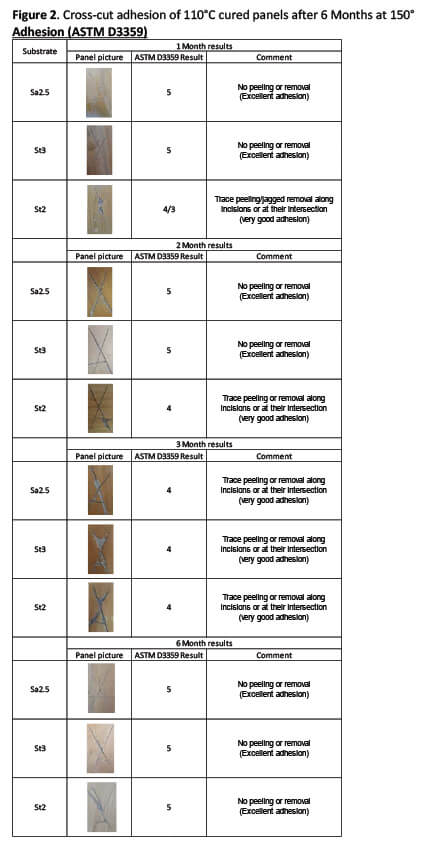
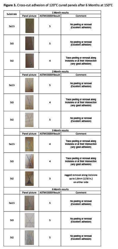
A proprietary product, which was formulated on the basis of micronised glass flake epoxy technology, has been evaluated to determine the effect of prolonged high temperatures on it after being applied to Sa2.5 blasted, and St2 and St3 hand prepared steel, at high temperatures (110C and 120C) and then stored at 150C, in comparison to when applied and kept at ambient temperature. In summary, the testing on heat aged samples showed that there was very little change on cross cut adhesion (ASTM D3359) over 1-6 months (see Figures 2 and 3); no or other deterioration of the film was observed after 6 months heat ageing, and Thermogravimetric Analysis (TGA) showed no weight loss in the samples test up to 6 months in test area i.e. 150C (Figure 4).
These results show that the formula is thermally stable at 150C and has good adhesion to a range of substrates with good film integrity.
Conclusions
Coatings specifications based on micronised glass flake epoxy technology have been developed which will allow paint application onto hand prepared steel at elevated substrate temperatures up to 120C, and with a maximum operating temperature of 150 C,without the necessity of shutting down high temperature industrial processes. Such coatings will allow straightforward maintenance solutions under challenging conditions, typically found in O&G offshore and other Energy operations, where extensive surface preparation is not possible. Other differentiated value propositions of the technology deliver time and cost savings through up to 400µm dry film thickness build in a single brush coat, suitability for application with airless spray as well as brush and roller and aesthetically pleasing appearance in comparison to conventional epoxy glass flake epoxies. All of these operational and application benefits are complemented with an outstanding long term anti-corrosion performance through micronised glass flake epoxy technology.
The November meeting was held at the Rosen Facility in Gosforth, and Barry Turner gave a presentation entitled, “A review of ISO 21809-3 standard for field joint coating”. Barry has over 30 years’ experience in industrial coatings and plastics for the oil and gas and water industry. He has a strong technical background with experience in sales, marketing, development and technical service positions, and is an active participant in ISO standardisation development for pipeline coatings as UK nominated expert.
ISO 21809-3 is becoming the recognised standard for the qualification and testing of field joint coatings on steel pipelines in the Oil and Gas sector. Barry presented his personal review of the 2016 revision of the standard and tried to put some light on the standard development process and explain the different material classes and associated issues and concerns. The presentation started with a historical look at the qualification of field joint coatings (FJC), viz:
DIN 30672-1 (2000) – Joint DIN/DVGW developed standard for tapes and shrinkable materials, with no cathodic protection, and max. temperature 50ºC.
EN 12068 (1999) – developed under CEN leadership for tapes and shrinkable materials, with cathodic protection, material defined maximum temperature, and offshore and “special situations” are excluded.
NF A49-716 (1998) – replaced by EN 10329 in 2006.Covers 8 different coating types, as very diverse materials unable to standardise requirements. End user to chose coating type.(EN 10329 based on similar philosophy to 49-716).
The presentation then moved on to the dominant standard in North America, CSA Z245.30 (2014) developed by Canadian Standards, and which is a mandatory requirement in Canada for FJC,but also for field applied coatings in general, covers 7 material classes. It also defines responsibilities of each party involved in a coating job and the qualification of materials, application procedures and individuals as applicators.ISO 21809-11 is new and currently being drafted and will similarly be for field applied coatings but looking more toward external coating’s rehabilitation in the field. The bulk of the discussion held was on the ISO 21809 standard and especially the different coatings classes, ie., Part 1, Polyolefin coatings (3-layer PE and 3-layer PP) and currently under revision; Part 2, Single layer fusion bonded epoxy coatings; Part 3, Field joint coatings; Part 4, Polyethylene coatings (2 layer PE) ; Part 5, External concrete coatings ; Part 6, Dual layer and Multi layer fusion bonded epoxy coatings (NEW, currrently in development);
and Part 11, Coatings for in-field application, coating repairs and rehabilitation.
Everyone that attended found the talk very informative and resulting in a lot of discussion.
Following on from the successes of the previous YEPs, the next Young Engineer Programme will start in January 2018.
Lectures will cover, basic corrosion, welding, materials, coatings, painting, fire protection and linings, cathodic protection, chemical treatments, and will include presentation skills. We are currently carrying out pre-enrolment for this programme, and are seeking engineers in the early stages of their career in the corrosion industry, and who are looking for extra experience to set them up for their future.
If you are interested in this event please fill in the application form which can be obtained from Institute of Corrosion, Barratt House, Kingsthorpe Road, Northampton, NN2 6EZ, or email, admin@icorr.org. Deadline for receipt of applications is mid December 2017.
On November 8th, Young ICorr hosted a joint young engineering networking event in collaboration with The Welding Institute and the London Materials Society, at the TimberYard in Soho, London. The evening brought together fifty young engineers, professionals and students who are interested in corrosion, materials, metallurgy and welding, and it was a great opportunity to meet like-minded peers from other industries and to allow an opportunity
to network.
The evening’s guest speaker, Dr. Adam Baker, gave a thrilling talk about the materials challenges of rocket engineering and spaceflight. Since studying Materials Science and Metallurgy at The University of Oxford, Dr. Baker has spent his career working in the space industry and currently both teaches part-time at Kingston University and consults widely on space technology. Dr. Baker’s enthusiasm for the UK space industry was palpable as he explained why rockets are needed, the different propulsion technologies and the materials and corrosion engineering challenges associated with the extreme environments they experience.
Sponsorship was kindly provided by the Institute of Corrosion and The Welding Institute. To stay informed about future Young ICorr events please join the LinkedIn group by searching for ‘Young ICorr’ or alternatively email chris.bridge@uk.bp.com
We use cookies to optimize our website and our service.
Functional
Always active
The technical storage or access is strictly necessary for the legitimate purpose of enabling the use of a specific service explicitly requested by the subscriber or user, or for the sole purpose of carrying out the transmission of a communication over an electronic communications network.
Preferences
The technical storage or access is necessary for the legitimate purpose of storing preferences that are not requested by the subscriber or user.
Statistics
The technical storage or access that is used exclusively for statistical purposes.The technical storage or access that is used exclusively for anonymous statistical purposes. Without a subpoena, voluntary compliance on the part of your Internet Service Provider, or additional records from a third party, information stored or retrieved for this purpose alone cannot usually be used to identify you.
Marketing
The technical storage or access is required to create user profiles to send advertising, or to track the user on a website or across several websites for similar marketing purposes.