Improved Electrochemical Corrosion  Testing in Extreme Conditions:  Collaborative Advances in Autoclave Testing

Improved Electrochemical Corrosion Testing in Extreme Conditions: Collaborative Advances in Autoclave Testing

‘Amber Sykes¹, Danny Burkle², Robert Jacklin1,2 Joshua Owen¹, R Woollam¹, R Barker¹
¹School of Mechanical Engineering, University of Leeds, UK | ²LBBC Baskerville, UK

Amber Sykes is currently a PhD student at the University of Leeds, within the Institute of Functional Surfaces, where she is researching iron carbonate corrosion product formation in geothermal environments. Prior to her PhD research, Amber gained a Master of Engineering (MEng) degree in Mechanical Engineering at the University of Bath. During 2024 she received an EFC – European Federation of Corrosion Award for Best Oral Presentation by an Early Career Author.


]Dr Danny Burkle, is a Principal Engineer and corrosion testing specialist at LBBC Baskerville. He earned his Master’s Degree in Mechanical Engineering and a PhD in Corrosion from the University of Leeds. With over 10 years’ experience dedicated to the corrosion field, he is a professional member of the Institute of Corrosion (ICorr) and formerly the chair of Young ICorr, Danny now leads the ICorr Corrosion Engineering Division (CED). His contributions to corrosion research have included 6 published journal papers as the lead author and over 10 papers as a named author/contributor. He joined LBBC in 2017 through a KTP – Knowledge Transfer Partnership with the University of Leeds, Danny and has since progressed seamlessly from a Design Engineer to a Principal Engineer. His trajectory has a strong focus on business development and sales related to the research sector.

1. Introduction: Why Collaboration Matters

This article highlights a collaborative approach in developing a test method to obtain high-quality, reproducible electrochemical data within an autoclave operating at elevated pressure and temperature.

The evaluation and understanding of material corrosivity in high-pressure, high-temperature (HPHT) environments is critical to ensuring asset integrity in industries such as Oil and Gas, Carbon Capture and Storage (CCS) and Geothermal Energy to name a few. Carbon steel processing infrastructure in these systems is frequently exposed to carbon dioxide (CO2)-containing fluids, accelerating corrosion and threatening long-term integrity.

Under specific CO2 – containing conditions—particularly elevated temperature, pressure, and chemical saturation—the corrosion product iron carbonate (FeCO3) can precipitate onto the internal surfaces of carbon steel pipes. This layer can slow degradation by blocking active corrosion sites and impeding the diffusion of electrochemically active ions [1]. Understanding the formation, structure, and protective mechanisms of FeCO3 layers is therefore vital for accurate corrosion modelling and prediction, and hence asset integrity management.

Autoclave technology can facilitate experimental corrosion testing in HPHT environments, in which protective FeCO3 layers tend to form. In-situ electrochemical monitoring techniques, such as Linear Polarisation Resistance (LPR) and Electrochemical Impedance Spectroscopy (EIS), can provide real-time insight into the rate of FeCO3 layer formation, and the evolving mechanisms of corrosion protection offered by the layer. However, the application of these techniques in HPHT conditions remains exceptionally challenging. Issues such as reference electrode instability, electrical interference, and difficulty maintaining test equilibrium often lead to poor data reproducibility and limit the utility of these techniques for model development and material evaluation.

To address this gap, a collaborative project between LBBC Baskerville and the University of Leeds has advanced the reliability and precision of electrochemical testing in autoclaves. By combining industrial design expertise with academic electrochemical research, the team has developed a refined methodology capable of delivering high-quality, reproducible electrochemical data under extreme conditions.

This article presents two core outcomes of that collaboration:

1.How a refined testing methodology enables reproducible monitoring of corrosion product formation in autoclave conditions.

2.How this data supports advanced EIS modelling to quantify the layer’s physical properties in an autoclave.

Together, these insights offer a practical foundation for enhancing corrosion prediction in real-world HPHT systems.

2. Experimental Set-Up: Refining the Approach

The collaborative work began by identifying recurring limitations in electrochemical autoclave testing. Robert Jacklin’s PhD research project at University of Leeds played a key role in diagnosing failure points, including pressure instability, signal drift, and inconsistent electrode positioning [2].

The team developed a refined procedure using the LBBC Baskerville CTA-S1300 autoclave, incorporating:

•Improved sealing methods and sample insulation to prevent electrical interference,

•A low-pressure CO2 sparging method to pre-saturate the brine prior to solution transfer,

•Careful arrangement of working, counter, and reference electrodes to avoid electrical interference,

•Use of a back pressure regulator (BPR) to maintain consistent test pressure during heating.

Electrode Preparation and Assembly

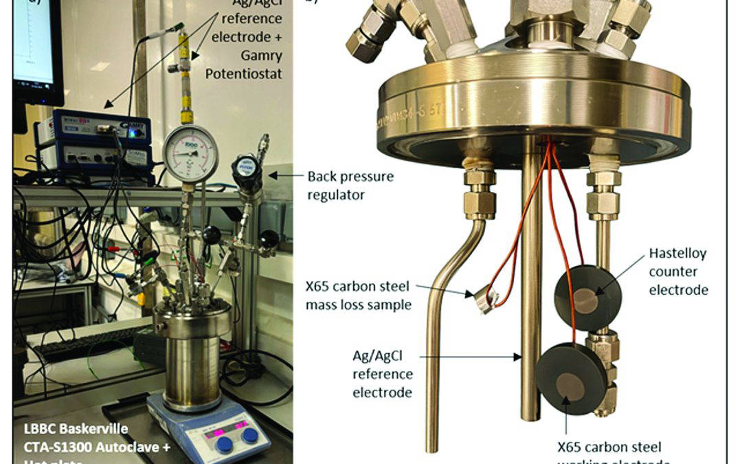
A three-electrode set up was used to take in-situ electrochemical measurements, including an X65 carbon steel working electrode, a Hastelloy C-276 counter electrode and an externally pressure balanced silver/silver chloride (Ag/AgCl) reference electrode. The working and counter electrodes were prepared by wet grinding all surfaces to P600 grit and sealing the back and sides with high-pressure thermosetting resin. An additional X65 carbon steel coupon was prepared for each test to assess mass loss. The arrangement of the electrochemical samples and mass loss coupon in the autoclave is shown in Figure 1.

Brine Preparation and Autoclave Testing Procedure

A 3 wt.% sodium-chloride (NaCl) brine was prepared by dissolving >99 % purity NaCl in deionised water, followed by stirring and continuous CO2 sparging for a minimum of 12 hours to ensure oxygen removal and full saturation. The 1.3L LBBC Baskerville autoclave was also flushed through with CO2 for a minimum of 30 minutes before the brine solution was transferred into the autoclave by CO2 gas displacement.

The autoclave was pressurised to the desired operating pressure (5, 10 or 15 bar) using a high-pressure CO2 line at room temperature, followed by heating to 80 °C using a hot plate and temperature probe. A BPR maintained the test pressure during the heating phase. Upon reaching the target temperature, the outlet valve to the BPR was closed and the pressure in the autoclave was allowed to evolve naturally throughout the test. The working, counter and reference electrodes were connected to a Gamry Potentiostat to take electrochemical measurements. The autoclave vessel was grounded through a metal hot plate [2].  An image of the autoclave set up is shown in Figure 1.

Electrochemical testing followed a repeatable schedule: Open Circuit Potential (OCP), five cycles of LPR, and EIS scans. This setup significantly improved baseline stability and reduced variability across runs. These methods were carefully documented and refined through repeated testing, highlighting how hardware design, procedural control, and pressure regulation directly influence
data quality.

This approach was initially used to refine the procedure and ensure high-quality, reproducible measurements at 5 bar, before being applied in tests at 10 and 15 bar to evaluate reproducibility and environmental sensitivity.

3. Reproducibly Tracking FeCO2 Layer Formation in Autoclaves

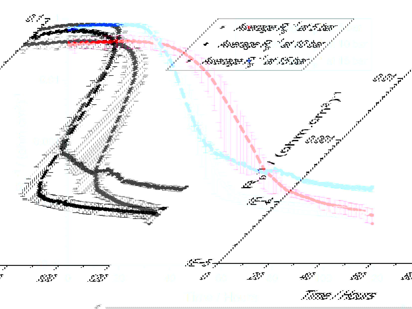
The LPR results in Figure 2 were obtained using the refined autoclave testing set up and show how the average inverse polarisation resistance (Rp-1) varied throughout the 120-hours corrosion tests at 5, 10 and 15 bar. Rp-1 is directly proportional to the corrosion rate of the underlying carbon steel surface. The error bars represent the range in Rp-1 values across four repeats at 5 bar and two repeats at 10 and 15 bar.

The evolution of a protective FeCO3 layer was initially investigated at 80 °C and 5 bar.

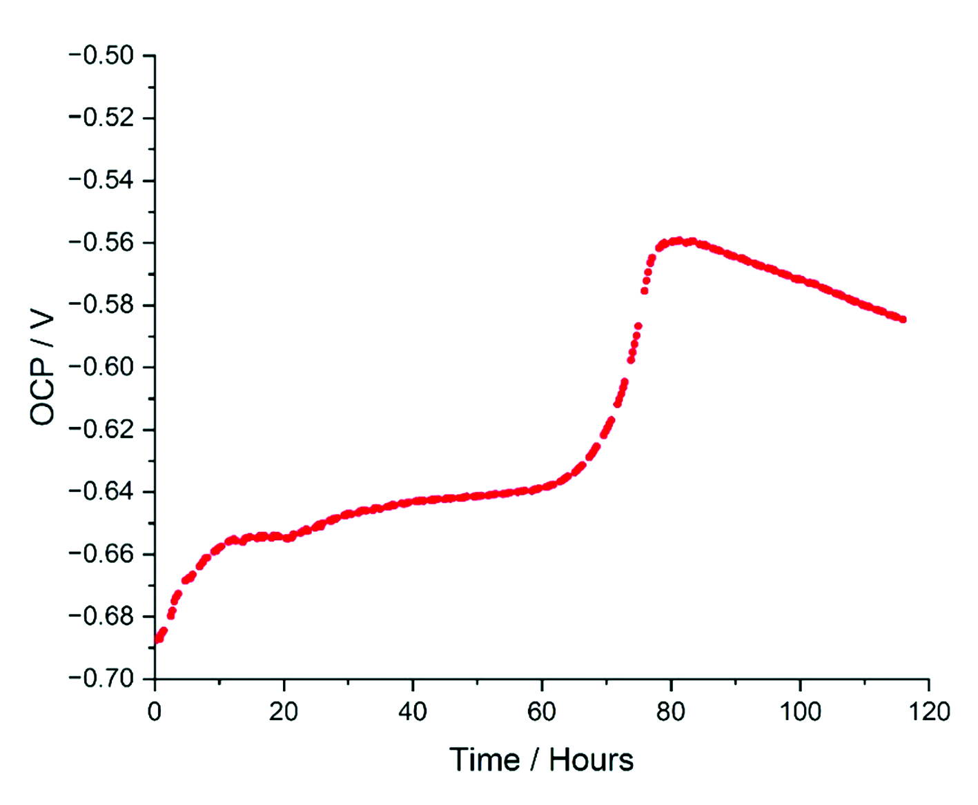
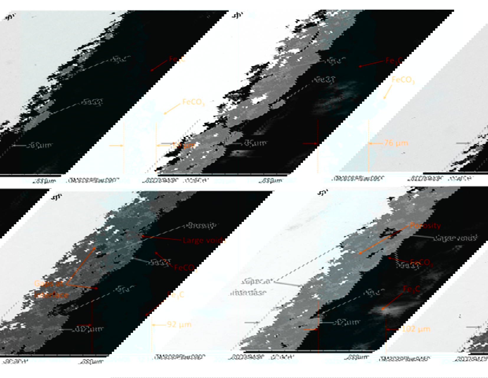
At these conditions, a rapid decrease in corrosion rate occurred after the first 40 hours of exposure, aligning with the onset of FeCO3 precipitation. The EIS Nyquist plots also showed a change in shape from two distinct semi-circles to the formation of a low-frequency linear tail, shown in Figure 5, indicating the transition from active corrosion to a diffusion-limited processes. At this point, the mechanism of protection offered by the FeCO3 layer transitioned from predominantly surface blocking to effectively restricting the diffusion of ions [1]. This occurred alongside the ‘pseudo-passivation’ phenomenon, between 70 and 80 hours, marked by a sudden anodic shift in OCP, shown in Figure 3, and a plateau in polarisation resistance [4]. The cross-sectional scanning electron microscopy (SEM) images in Figure 4 confirm the evolution of a low-porosity FeCO3 layer, consistent with the formation of an effective diffusion barrier, supporting the electrochemical interpretations. These findings validated that the new autoclave methodology could reproducibly capture the entire corrosion-product evolution timeline, from initial exposure through to protective film formation.

The LPR results in Figure 2 also show that the refined autoclave testing methodology could capture repeatable electrochemical measurements in more demanding environments, and with accelerated corrosion kinetics. Increasing the operating pressure from 5 to 15 bar resulted in higher initial corrosion rates and a faster rate of formation of a protective FeCO3 layer [3]. These tests demonstrate the sensitivity of FeCO3 formation and corrosion characteristics to environmental changes and highlights the importance of experimental testing over a wide range of operating conditions.

4. Quantifying Layer Properties Using High-Precision EIS Modelling

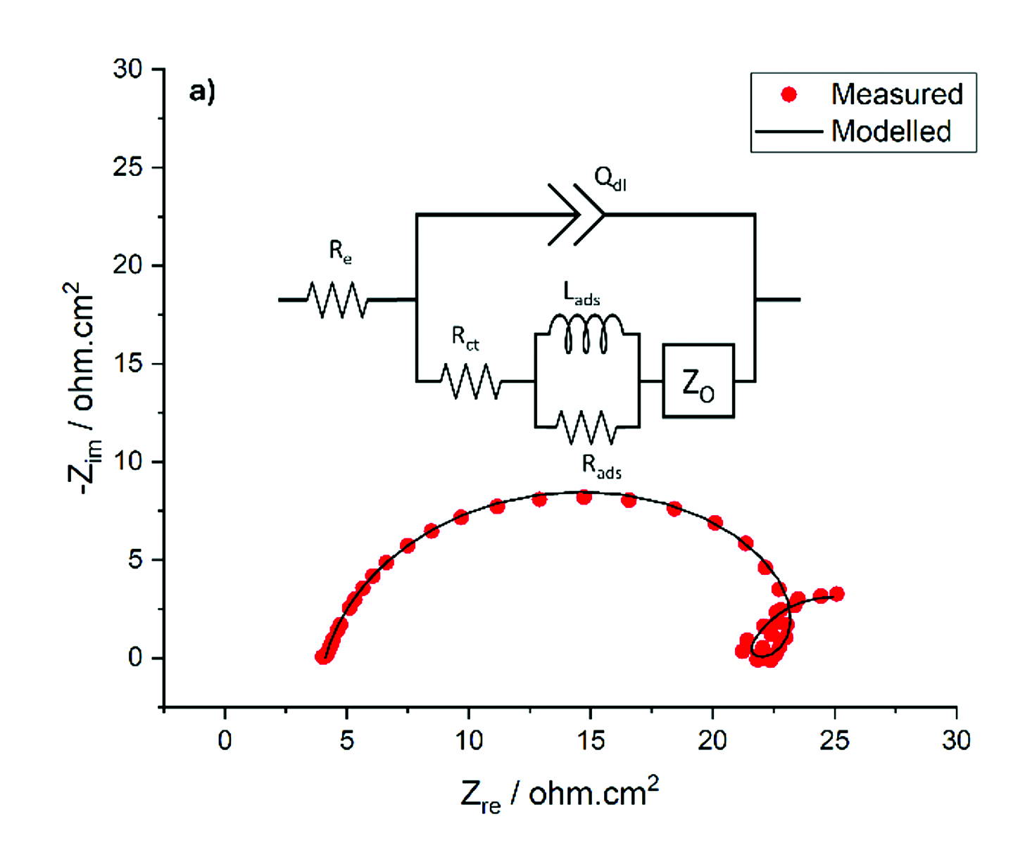
The LPR responses in Figure 2 show that corrosion product formation significantly alters the corrosion rate of the underlying carbon steel and must be considered for the accurate prediction of corrosion rates in HPHT environments. However, the current incorporation of FeCO3 into CO2 corrosion models relies on numerous theoretical assumptions regarding the physical properties of the layer, and how these properties contribute towards the mechanisms of corrosion protection [5]. To quantify the protectiveness of corrosion products layers throughout their development, and extract physical properties of FeCO3, equivalent electrical circuit models can be fit to the experimental EIS data.

] 

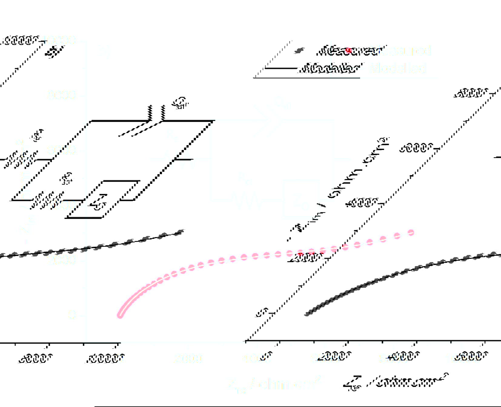
High-precision EIS data is required to obtain useful and reliable information from equivalent circuit models. To assess the quality of the experimental EIS data, Kramers-Kronig analysis is used. The Kramers-Kronig transformation assesses the validity of the EIS response by testing for linearity, causality and stability [6].  This assessment is particularly important for the low frequency EIS data, used to characterise diffusion behaviour. The time scales required for low frequency measurements are increased, such that the stability condition may not be achieved. Once the EIS data has been validated, the quality of fit between the modelled and measured EIS data is calculated using chi-squared analysis normalised by the degrees of freedom (x2/v). The circuit models illustrated in Figure 5 both achieve an excellent quality of fit to the experimental EIS data, achieving x2/v values of less than 0.0002.

The quality of the electrochemical data in this study was sufficient to extract the full low-frequency EIS response, enabling the quantification of diffusion characteristics through the FeCO3 layer. This represents a significant advancement, as such measurements have rarely been achieved under comparable high-pressure, high-temperature conditions. The circuit models illustrated in Figure 5 were used to quantify the extent of surface coverage from FeCO3, and the diffusion coefficients of ions through the layer. This allows the respective contributions of surface blocking and diffusion restriction towards the overall reduction in corrosion rate to be identified, information that is critical to the advancement of corrosion prediction models.

The physical porosity of the FeCO3 layer was also estimated from in-situ EIS measurements, showing promising agreement with results from literature [7]. Validating the use of electrochemical techniques to evaluate the porosity of corrosion product layers in-situ would be a landmark finding for this research area.

In this study, the development of a robust autoclave testing methodology enabled the collection of high-precision and meaningful EIS data in HPHT environments. Equivalent electrical circuit models could then be utilized to extract physical properties of the layer, in-situ, throughout the layer’s development – information which no other technique can provide.

Standardisation of electrochemical set-ups and autoclave testing procedures will continue to improve EIS data quality and facilitate innovative EIS studies that can further the development of corrosion prediction models and advance the knowledge of the wider corrosion industry.

5. Conclusion: A Path Forward Through Partnership

This collaboration between LBBC Baskerville and the University of Leeds has delivered two critical advances in autoclave corrosion testing:

• A validated methodology for reproducibly tracking FeCO3 layer formation under HPHT conditions using LPR, OCP, and EIS.

• The demonstration that precision EIS can be used to quantify key physical properties of corrosion product layers — such as surface coverage and diffusion characteristics.

These outcomes not only advance the science of corrosion but also provide practical tools and benchmarks for researchers and industry alike. Achieving reproducibility in HPHT electrochemical testing has long been a challenge; this work proves it is possible with the right approach. The success of this collaboration also emphasises a pressing need in corrosion testing to the wider community: standardised methodologies for electrochemical testing in autoclaves.

Without clear standards, comparing data across institutions becomes difficult, and model calibration remains speculative.  By publishing detailed methods and validating their approach, this project offers a foundation on which others can build.

The methods and findings shared here are intended to empower others facing similar challenges in autoclave corrosion testing. As CCS, hydrogen, and geothermal technologies continue to expand, the need for reliable, high-precision corrosion data will only grow. This study provides a blueprint for how that data can be generated and used.

Next Steps: The team welcomes further collaboration to extend this methodology to multi-impurity systems and operational-scale environments. For more information or to explore partnership opportunities, contact Dr Danny Burkle (LBBC) and Professor Richard Barker (University of Leeds).

6. References

[1] R De Motte et al., E Basilico, R Mingant, J Kittel, F Ropital, P Combrade, S Necib, V Deydier, D Crusset, S Marcelin, “A Study by Electrochemical Impedance Spectroscopy and Surface Analysis of Corrosion Product Layers Formed During CO2 Corrosion of Low Alloy Steel”. Corrosion Science 172, (2020): p. 108666.

[2] R Jacklin, Characterising Protective Corrosion Product Development in Demanding CO2 Environments. Doctor of Philosophy thesis, University of Leeds, 2023.

[3] A Sykes et al., R Jacklin, D Burkle, R C Woollam, J Owen, R Barker, “The Effect of CO2 Partial Pressure on the Formation and Protective Characteristics of Iron Carbonate Corrosion Products”. AMPP Annual Conference + Expo, paper no. AMPP-2024-20666 (New Orleans, Louisiana, USA: Association for Materials Protection and Performance, 2024).

[4] W Li et al., B Brown, D Young, S Nešić, “Investigation of Pseudo-Passivation of Mild Steel in CO2 Corrosion”. Corrosion 70, (2014): p.
294-302.

[5] M Nordsveen et al., S Nešić, R Nyborg, A Stangeland, “A Mechanistic Model for Carbon Dioxide Corrosion of Mild Steel in the Presence of Protective Iron Carbonate Films-Part 1: Theory and Verification”. Corrosion 59, 5 (2003): p. 443-456.

[6] A Lazanas, M  Prodromidis, Electrochemical Impedance Spectroscopy – A Tutorial. ACS Measurement Science Au. 2023, 3.

[7] R Barker et al., D Burkle, T Charpentier, H Thompson, A Neville, A review of iron carbonate (FeCO3) formation in the oil and gas industry, Corrosion Science, Volume 142, 2018.

AI-Based Predictive Maintenance Framework for Online Corrosion  Survey and Monitoring

AI-Based Predictive Maintenance Framework for Online Corrosion Survey and Monitoring

Dr Shahrizan Jamaludin, Ph.D., P.Tech., is a senior lecturer in the Program of Maritime Technology and Naval Architecture at the Faculty of Ocean Engineering Technology, Universiti Malaysia Terengganu, Malaysia. In this role, he is responsible for the development of computer vision and image processing algorithms for marine structures maintenance. He brings 16 years of experience as a project engineer and research officer to the role. He is a graduate of the Electronic and Computer Engineering program from Universiti Teknikal Malaysia Melaka. His research interests include, but are not limited to, remote inspection technique, image processing, computer vision, pattern recognition, computer engineering, electronics, industrial automation, robotics and remote sensing for marine applications.

]]Md Meherullah is a master’s student at the Faculty of Ocean Engineering Technology, Universiti Malaysia Terengganu. His field of study is electronics, with a focus on automation and control. He completed his bachelor’s degree in Electronics and Communication Engineering (ECE) at Khulna University, Bangladesh. His research interests include image processing, the Internet of Things (IoT), pattern recognition, electronics, robotics and remote sensing.


 Introduction

Corrosion poses significant challenges to the structural durability, longevity, and integrity of marine infrastructure and shipping worldwide due to the increasing costs of maintenance, spare parts, component replacements, and the risk of catastrophic structural failures [1]. The corrosion processes affecting marine structures and vessels are influenced by operational conditions, material properties, and environmental factors, including the corrosive nature of seawater driven by salinity, pH, temperature, electrolyte composition, and oxygen concentration [2]. Therefore, it is essential to regularly or periodically monitor and inspect the condition of metallic components in marine structures and ships. Traditional methods—such as predictive models, electrochemical tests, and visual inspections—are often inadequate for highly complex structures, large-scale hulls, labour-intensive and hazardous environments, and early-stage corrosion detection. These limitations highlight the need for more efficient, reliable, accurate, and advanced technologies for corrosion survey, inspection, and maintenance.

In recent years, Artificial Intelligence (AI), particularly machine learning and deep learning, has emerged as a transformative approach in corrosion research. Although AI does not replace the requirement for peer review and engineering competency, AI does enable the analysis of vast datasets, the identification of hidden patterns, and the generation of precise predictions regarding corrosion behaviour under varying conditions [3]. Techniques such as Convolutional Neural Networks (CNNs), Vision Transformers, Random Forests, and others have been applied to corrosion surveying [4], inspection [5], and maintenance [6], as documented in current literature. These AI methods are increasingly being integrated with traditional techniques to enhance and improve outcomes. Predictive maintenance, in particular, is an essential AI-driven strategy that aims to determine the optimal timing for maintenance activities, especially concerning structural integrity and corrosion in marine environments. Its main advantages include cost reduction, increased safety (automation reduces human intervention), minimisation of unplanned downtime, and support for environmental sustainability [7]. However, the predictive maintenance framework for corrosion monitoring remains underdeveloped and sparsely reported in the literature [8]. Notably, there is a lack of a comprehensive framework addressing sensor systems, data storage and management, predictive modelling and analytics, and the deployment of Remote Inspection Techniques (RIT). Hence, this research aims to propose a predictive maintenance framework for corrosion monitoring using AI. The main contributions of this study are:

1. A predictive maintenance framework for AI-based corrosion monitoring that includes several key components working together to anticipate structural failures and optimise the timing of corrosion maintenance on marine structures and ships.

2. RIT regulations, particularly for drone or Unmanned Aerial Vehicle (UAV), Remotely Operated Vehicle (ROV), Unmanned Surface Vehicle (USV), unmanned robotic arm, and crawler/climber, that standardize and regulate the operation of RIT at sea in compliance with International Association of Classification Societies (IACS) recommendations and International Maritime Organization (IMO) standards when deployed on ships and vessels for survey, inspection, classification, and maintenance.

3. The developed framework aims to standardise the process and organisation of AI-based predictive maintenance for corrosion monitoring, making it easier to regulate globally, especially for marine structures
and ships.


The Framework

The framework is developed with four key components which are RIT deployment, sensor systems, data storage and management, and predictive modeling and analytics.

• Component 1 – RIT deployment, focuses on establishing a set of regulations and operational procedures for RIT tools and equipment, including drone, ROV, USV, crawler, climber, and unmanned robotic arms, particularly for use on ships.

• Component 2 – Sensor systems which can either be installed directly on marine structures or integrated with RIT tools to collect various types of data, including image data in the infrared or visible spectrum using optical sensors [9].

• Component 3 – Data storage and management. The large volume of data collected from sensors necessitates the use of cloud-based big data storage systems for efficient management and analysis. Reliable communication and data transfer between the sensors and the cloud are crucial to enable real-time analysis with high accuracy [10]. Multiple communication protocols must be established to ensure data integrity in uncontrolled and harsh marine environments.

• Component 4 – Predictive modeling and analytics. Predictive models are developed using historical and real-time data related to corrosion parameters on marine structures and ships [11]. The proposed framework is illustrated in Figure 1 below.

RIT Deployment

The first component in the framework is RIT deployment. RIT refers to methods used to examine parts of marine or ship structures without requiring direct physical access [12]. The maritime industry is increasingly adopting RIT, as these techniques offer greater efficiency, higher flexibility, and improved reliability in the day-to-day operations of survey and inspection, without compromising the quality of the results [13]. Various RIT tools or equipment can be used for marine structures and ships, depending on the shapes and surfaces involved. Drones are particularly flexible for surveys and inspections, as they can access open spaces, hard-to-reach areas, elevated locations, hazardous zones, and confined spaces [14]. Meanwhile, ROVs are used for underwater inspections where other RIT tools cannot operate [15]. Since visibility underwater is often moderate or poor, high-quality optical sensors are required for effective inspection. USVs are used to inspect structures near the water surface [16]. Crawlers or climbers are suited for hull inspection and maintenance while the ship is sailing and far from the coast [17]. Unmanned robotic arms can also be utilised to access parts of marine and ship structures that are otherwise difficult for humans to reach [18]. Following the surveying and inspection processes conducted using RIT tools, maintenance activities can be planned and executed accordingly. These tools scan marine structures and ship compartments systematically, and predictive maintenance systems then analise the data to support real-time maintenance decision-making and implementation. The ship
affected with corrosion is illustrated in Figure 2.

Moreover, all RIT tools deployed on ships must comply with the recommendations and standards set by IACS and IMO to ensure the safety and well-being of workers and assets. IACS Recommendation 42 (Guidelines for Use of Remote Inspection Techniques for Surveys) outlines the controlled use of RIT to enhance survey processes, emphasising that these techniques are supplementary and must be conducted under strict guidelines to ensure safety and regulatory compliance. According to IACS Recommendation 42, all RIT operations must be witnessed by an attending surveyor to validate the inspection. RIT tools must be properly calibrated and tested before use, and the operators conducting the inspections must be qualified. An inspection plan detailing the RIT methods, equipment, and procedures must be submitted in advance for review and approval. Regarding inspection conditions, the structures must be sufficiently clean to allow meaningful examination, and visibility must be adequate for accurate assessment. For data handling, effective two-way communication between the surveyor and the RIT operator is essential. The surveyor must be satisfied with the quality of the data presentation, including visual representations.

Despite the advantages of RIT, its use for close-up surveys under specific conditions in ship inspections remains restricted or limited due to concerns related to the health, safety, and accuracy of RIT tools and associated assets. If such conditions are detected, traditional close-up surveys may be required. To address this, IACS has proposed amendments to the 2011 ESP Code to incorporate more technical procedures for RIT, including the formal definition of RIT within the code, permission for its use in close-up surveys, and the establishment of specific requirements for RIT applications. Furthermore, it is important to differentiate between RIT and remote surveys in the context of the code. RIT involves the physical attendance of a surveyor using remote tools to inspect areas that are difficult to access, while remote surveys are conducted without the physical presence of a surveyor, typically relying on electronically transmitted data. It is essential to note that the use of RIT is restricted in situations where conditions of class for repairs are imposed, or when there is a record or indication of abnormal deterioration or damage. Additionally, the proposed amendment supports the use of RIT to assist surveyors in their inspection tasks without compromising the accuracy or integrity of the surveys. When RIT is employed for close-up surveys, temporary access means must be provided for thickness measurements unless the RIT system is also capable of performing those measurements. In this context, ultrasonic thickness gauges can be installed on RIT equipment to allow simultaneous data collection. The amendment to the 2011 ESP Code has the potential to enable safer surveys, reduce inspection errors, and lower maintenance costs, particularly in corrosion-related cases. The details of 2011 ESP Code amendment can be referred here [19]. Figures 3 show the RIT implementation using drone and climber for ship survey and inspection.

Sensor Systems

The second component in the framework is the sensor systems. Vibration, temperature, humidity, pressure, acoustic, optical, and ultrasonic thickness measurement sensors can be used to survey marine and ship structures. These sensors must be durable enough to operate in harsh marine environments. They can either be equipped on RIT tools or directly installed on the structures. These sensors continuously monitor the health of structures and equipment to detect early signs of degradation. According to the amendment to the 2011 ESP Code, RIT must provide the extent and quality of information normally obtained from a close-up survey. This means that the sensor systems must be reliable and deliver accurate data to assist the surveyor. The data collected from the sensors will serve as input for predictive modeling, and the output from the predictive models will be presented to the surveyor. The surveyor must be satisfied with the method of data presentation, including pictorial representations of corroded areas on the structures, in order to verify the results of predictive maintenance. For network communication between sensors and the cloud, options include Wi-Fi, cellular (4G/5G), Long Range Wide Area Network (LoRaWAN), Ethernet, or RS-485. Edge devices or computing platforms such as Raspberry Pi, Arduino, ESP32, and others can be used to convert, filter, compress, and transmit sensor data to the cloud via these communication networks. Common communication protocols include MQTT and HTTP/HTTPS, which are widely used for transmitting messages and data between servers and clients.

Data Storage and Management

Once the data from sensors, transmitted via edge devices, reaches the internet through a gateway or direct connection, it is sent to a cloud platform such as AWS IoT Core, Azure IoT Hub, Google Cloud IoT Core, MATLAB ThingSpeak, or other cloud services. Those cloud services are tailored for IoT applications. The types of data may include time-series data, images, and logs. In the cloud, the transmitted data is managed based on the surveyors’ tasks. It is pre-processed to remove noise, handle missing values or outliers, and apply appropriate data labeling. All data is securely stored, and data analytics can be performed online using either existing AI models or models developed by the surveyors. The data is processed accordingly and then stored for future use. The cloud facilitates real-time data processing from the sensors and supports long-term trend analysis, which is essential in the context of corrosion monitoring. Effective data management ensures that historical corrosion trends are captured, and the data can be accessed or visualised on demand.

Predictive Modeling and Analytics

This component involves turning raw sensor data into actionable insights about when and where corrosion will occur, how fast it is progressing, and when intervention is needed. AI-based predictive modeling can identify and quantify corroded regions, as well as forecast corrosion rates with high accuracy. Machine learning and statistical models are applied to predict future failures or RUL, detect the early onset of corrosion through anomalies, and trigger maintenance alerts before failures occur.

These predictive models can include decision trees, neural networks, support vector machines, or other AI-based methods. For corrosion rate estimation, data-driven methods such as machine learning regression can be used. For RUL estimation, models like random forests or Long Short-Term Memory (LSTM) networks may be applied. For anomaly detection, techniques such as k-means clustering or autoencoders can be utilized. For image analysis, vision transformers or CNNs are suitable. For corrosion risk scoring, support vector machines or Naive Bayes classifiers can be employed. Common tools for AI model development include TensorFlow, Google Colab, MATLAB, XGBoost, OpenCV, PyTorch, and Keras. Despite the methods mentioned above, there are no strict restrictions on which AI models can be used for each application or case. Once a potential failure is predicted by the models, decision-making tools assist in determining the optimal maintenance actions, taking into account factors such as cost, downtime, and risk. Predictive outputs should be integrated into enterprise systems (e.g., CMMS, ERP) to automatically trigger work orders or adjust operations. However, in the context of ship surveys, IACS Regulation 42 and the 2011 ESP Code amendment mandate that RIT support surveyors in their close-up survey activities without impairing the quality of the surveys. At the same time, surveyors must verify the results produced by RIT and predictive maintenance. This means the output from predictive maintenance will assist surveyors in making informed decisions regarding the structural integrity of ship structures.

Conclusions

Our global maritime industry is increasingly adopting RIT for marine structures and ship applications. The integration of predictive maintenance with RIT for surveys, inspections, and maintenance enhances efficiency and accuracy without compromising the results of conventional surveys. The proposed new framework provides real-time condition monitoring in place of periodic inspections, early warnings of hidden damage (such as corrosion under insulation), optimized inspection schedules (condition-based rather than time-based), better resource allocation, and non-invasive detection methods. These improvements can reduce the risk of sudden leaks, failures, or environmental incidents, while also enabling data-driven decisions with quantified confidence. Additionally, the proposed framework contributes to standardising the processes and organisation of AI-based predictive maintenance for corrosion monitoring, particularly in the context of surveying, inspection, and maintenance of marine and ship structures. It is evident that the prediction output from the framework will assist surveyors in making informed decisions regarding the structural integrity of marine and ship structures, especially in the context of corrosion. In the future and with input from competent engineering resources, AI models can be further fine-tuned to improve the effectiveness of predictive maintenance outputs in supporting surveyors’ decision-making.

References

[1]  M M H Imran et al., A Critical Analysis of Machine Learning in Ship, Offshore, And Oil and Gas Corrosion Research, Part I: Corrosion Detection and Classification, Ocean Engineering 313 (2024). 119600. https://doi.org/10.1016/j.oceaneng.2024.119600

[2]  I M Chohan et al., Effect of Seawater Salinity, Ph, And Temperature on External Corrosion Behavior and Microhardness of Offshore Oil and Gas Pipeline: RSM Modelling and Optimization, Scientific Reports 14(1) (2024). 16543. https://doi.org/10.1038/s41598-024-67463-2

[3]  W Liang et al., Advances, Challenges and Opportunities in Creating Data for Trustworthy AI, Nature Machine Intelligence 4(8) (2022). 669-677. https://doi.org/10.1038/s42256-022-00516-1

[4]  O A Oyedeji, S. Khan, J A  Erkoyuncu, Application of CNN for Multiple Phase Corrosion Identification and Region Detection, Applied Soft Computing 164 (2024). 112008. https://doi.org/10.1016/j.asoc.2024.112008

[5]  A Subedi et al., CorFormer: A Hybrid Transformer-CNN Architecture for Corrosion Segmentation on Metallic Surfaces, Machine Vision and Applications 36(2) (2025). 45. https://doi.org/10.1007/s00138-025-01663-2

[6]  M  Gavryushina et al., A  Marshakov, Y. Panchenko, Application of the Random Forest Algorithm to Predict The Corrosion Losses of Carbon Steel Over the First Year of Exposure in Various Regions of The World, Corrosion Engineering, Science and Technology 58(3) (2023). 205-213. https://doi.org/10.1080/1478422X.2022.2161336

[7]  M M H Imran et al., Effective Periodic Noise Reduction for Ship Corrosion Image, Journal of Advanced Research Design 129(1) (2025). 130-147. https://doi.org/10.37934/ard.129.1.130147

[8]  M M H Imran et al., Advanced techniques in ship corrosion analysis: integrating active contour algorithms for image segmentation, Journal of Advanced Research Design 128(1) (2025). 79-99. https://doi.org/10.37934/ard.128.1.7999

[9]  T  Hasan, et al., S Jamaludin, W B W  Nik, Details Design Strategy Analysis of A Hybrid Energy System Boat in Efficient Way, Jurnal Kejuruteraan 37(2) (2025). 555-561. https://doi.org/10.17576/jkukm-2025-37(2)-01

[10]  S Jamaludin, N Zainal, W M D W  Zaki, Comparison of Iris Recognition Between Active Contour and Hough Transform, Journal of Telecommunication, Electronic and Computer Engineering 8(4) (2016). 53-58

[11]  S Ayvaz, K Alpay, Predictive Maintenance System for Production Lines in Manufacturing: A Machine Learning Approach Using Iot Data in Real-Time, Expert Systems with Applications 173 (2021). 114598. https://doi.org/10.1016/j.eswa.2021.114598

[12]  M Meherullah et al., Accurate Corrosion Detection and Segmentation on Ship Hull with Pixel Property Method, Journal of Advanced Research Design 129(1) (2025). 148-163. https://doi.org/10.37934/ard.129.1.148163

[13]  T M Johansson et al., A  Pastra, M Q  Mejia, Seaworthiness and Protecting the Ocean: Maritime Remote Inspection Technologies, The International Journal of Marine and Coastal Law 39(3) (2024). 551-560. https://doi.org/10.1163/15718085-bja10177

[14]  S Jamaludin et al., M M H Imran, Practical Application of Artificial Intelligence in Steel Corrosion Analysis, Corrosion Management 181 (2024). 38-41

[15]  S  Jamaludin, M M H  Imran, Artificial Intelligence for Corrosion Detection on Marine Structures, Journal of Ocean Technology 19(2) (2024). 19-24

[16]  N I M Jalal  et al., A F M  Ayob, S  Jamaludin, N A A  Hussain, Evaluation of Neuroevolutionary Approach to Navigate Autonomous Surface Vehicles in Restricted Waters, Defence S and T Technical Bulletin 16(1) (2023). 24-36

[17]  M  Shahrami, M  Khorasanchi, Development of a Climbing Robot for Ship Hull Inspection, Journal of Survey in Fisheries Sciences 10(1) (2023). 1-11.[18]  S.I. Wahidi, S. Oterkus, E. Oterkus, Robotic Welding Techniques in Marine Structures and Production Processes: A Systematic Literature Review, Marine Structures 95 (2024). 103608. https://doi.org/10.1016/j.marstruc.2024.103608

[19]  IACS, Amendments to the 2011 ESP code, Accessed on 1 May 2025. https://iacs.org.uk/news/iacs-participation-at-sdc-10

[20]  A  Ortiz, Vision-Based Corrosion Detection Assisted by A Micro-Aerial Vehicle in A Vessel Inspection Application, Sensors 16(12) (2016). 2118. https://doi.org/10.3390/s16122118

[21]  Remotion, A splash zone specialist, Accessed on 1 May 2025. https://remotion.no/our-systems/

2025 – Aberdeen Annual Corrosion Forum (ACF)

2025 – Aberdeen Annual Corrosion Forum (ACF)

On 26th August 2025 the Aberdeen Branch again successfully held its annual corrosion awareness event at the Palm Court Hotel with key sponsor Automa.

The Aberdeen branch has been active for more than 40yrs now and has been providing awareness training since before 2010 through generous industry support and a dedicated committee.

This year’s Forum was kindly sponsored by Automa of Italy, specialists in automated monitoring and themed on Cathodic Protection (CP).

Automa provided the Venue and all Catering for the day.

Introductory talks on the principles and costs of corrosion were followed by a series of talks explaining Cathodic protection principles, methods and anode manufacture. Thereafter some excellent case studies presented some recent Cathodic protection applications in order to raise awareness of some of the practical considerations such as electrical isolation from plant, electrical interference and fault-finding methods for CP system commissioning.

The afternoon sessions continued with several presentations by the sponsor Automa on advanced CP system monitoring and AI assisted data management and analysis. Automa then provided some excellent demonstrations of their devices and their software both widely used within Europe.

This popular Annual event attracted 43 registrants including many from its 16 local sponsor companies and also from our ICorr national sustaining companies.

Proceedings will be posted to the Aberdeen branch web page in due course at https://www.icorr.org/aberdeen/ ‘Local Technical Programme’

The Aberdeen ICorr Committee expresses its immense gratitude to all Attendees, Speakers, Sponsors and particularly to its Event Chairs – Eilidh MacDonald/Stephanie Okoye and to Fatemeh Faraji, the ABZ Events Coordinator.

On September 30th, 2025, the branch will host its first Event of the 2025-26 Technical Programme. This will be a Joint Event with the TWI North Scottish Branch and entitled ‘From Snapshots to Continuous Insight: Driving Maintenance Efficiency and Safety with Automated UT Monitoring by William Vickers of Ionix Advanced Technologies / Leeds, U.K.

Attendees will gain practical insight into how automated, non-invasive UT monitoring is being applied in the field today to enhance safety, optimise inspection programmes, and improve long-term asset performance.

Aberdeen welcomes your attendance at future events of the branch. Please contact icorrabz@gmail.com if you have any queries at all, or if you wish to join its committee.

Corrosion in Infrastructure Special Feature:  Inside Edinburgh’s £86M North 
Bridge Refurbishment

Corrosion in Infrastructure Special Feature: Inside Edinburgh’s £86M North 
Bridge Refurbishment

Article by Stephen Tate, Immediate Past President of ICorr

Introduction

It is not very often that such a well-documented corrosion repair project becomes available, but this key infrastructure link has made national news due to the extent of repairs required and, of course,
its huge cost!

On this same theme – ‘Reuse, Renew, or Replace?’ – Corrosion Management recently published several infrastructure-related articles presented to the Parliamentary and Science Committee, refer to https://www.icorr.org/wp-content/uploads/2025/03/CORROSION_MANAGEMENT_Issue183_48-pgs_LowRes.pdf

Photo 1:  The North Bridge in Edinburgh c. 1905.

.Background

It is one of Edinburgh’s most historically significant structures, a key transport link connecting the Old and New Towns and a vantage point to take in views of the capital’s iconic skyline – but for more than seven years now the North Bridge has been something of an eyesore, surrounded in scaffolding.

The North Bridge was originally constructed by Sir William Arrol between 1894 and 1897 after he completed both the Forth Bridge and Tower Bridge in London.

Since 2018 bridge has been concealed by over 300km of scaffolding tubes and partially closed to traffic and pedestrians after the Victorian structure was found to require significant corrosion-related repairs to ensure its continued use for future generations.

A repair project was initiated as a response to cast iron, spalled concrete and masonry falling onto the railway lines and the
street below.

Map: Location of North Bridge by Edinburgh Waverley Railway Station.

Structural Investigations

The bridge has three spans, each approximately 53 metres, with each span comprising six steel main arch girders with a reinforced concrete deck, masonry piers and abutments, and a decorative cast iron façade.

Photo 2: After Removal of Cast Iron Non-Structural Fascia.

Main contractor Balfour Beatty worked with Atkins Realis, who created a dynamic 3D model of the structure to assist all work scopes.

It became clear as the work progressed that more repairs and work were required. The paint on the bridge designed and constructed by Sir William Arrol, who created Forth Bridge and Tower Bridge, has been grit blasted and repainted – a job which has not been done since 1933, except for repainting of the decorative facings in the early 1990s.

Photo 3: Steel Under-Structure with Areas of Localised Corrosion Requiring Repair.

Investigations identified lots of Bimetallic Corrosion, Corrosion Traps between components, Water ingress and general Inadequate corrosion protection.

The huge complexity of bringing a Victorian structure up to 21st Century standards, without compromising its historic integrity, has proven challenging, technically and logistically.

Photo 4: Examples of Steelwork Repairs.

Costs

The work was supposed to take around two years and cost an estimated £22m, but as engineers took a closer look, often at sections not properly inspected in over 100 years, it became clear the job would be even more of a mammoth task than was first envisaged.

It is now expected to be finally completed in 2026 – six years behind schedule – and with an expected cost of £86m, nearly four times the initial estimate, but now magnificently restored!

Photo 5: Localised Reinforced Concrete Inspection/Repairs Including CP Installation and Structural Health Monitoring System – Reinforced Concrete Supports.

Photo 6: Cathodic Protection Junction Box and Site Connections.

Repairs Completed

There are 6,300 steel sections under the bridge, many of which were corroded, but now behind the extensive scaffolding have been repaired or replaced, approximately 2,000 components in total at a cost of £10m, due to complex logistics.

The wide scope of work has included:

•Contained wet blast/removal of existing coating – bituminous asbestos paint with arsenic, chromium and lead contaminants by licensed contractor. Asbestos was added to enhance durability, heat resistance, and fire resistance. The risks associated with asbestos exposure/removal are well-documented.

•Profile grit blasting and repainting of all structural steelwork, last renovated in 1933, 150 sqm to ST3 standard with 7-stage coating.

•Apply primer/stripe coat/mid coat/line gap/2nd stripe coat/topcoats and decorative colours/anti-graffiti finish.

•Repairing and refurbishing structural steelwork and cast-iron springer bearings.

•Refurbishing historic cast iron bridge façades, including the redesign of façade fixings, allowing for sectional movement and easier future repairs.

• Grit blasting, repair, sealing and repainting of parapets.

•Repairing the bridge’s concrete deck and installing cathodic protection and structural health monitoring systems.

o 6,500 Galvashield XP2 Anodes – subcontractor (Freyssinet)

o 40,778 Continuity Wires and Checks

• Repair and improve pavements and drainage.

• New waterproof membrane on bridge deck.

• New lighting and road surface.

•Remove all redundant utility pipes and ducts and rationalise those services that remain.

•Repair and repoint masonry in areas most susceptible to deterioration.

•Restore and repair the King’s Own Scottish Borderers War Memorial.

•Installing permanent platforms to improve access for future inspection and minor maintenance.

Photo 7: Process of Façade Reassembly.

Photo 7: Process of Façade Reassembly.

Photo 8: Reinstated North Bridge Façade and Final Touches.

Very complex scaffolding was required. Traditional scaffolding that relies on ground support could not be used and due to the interface with Edinburgh’s key railway station (Waverley) and the low capacity of the roof, scaffolding had to be suspended from the bridge itself. This required multiple stages of design and checks.

Photo 9: Steel Under-Structure After Repair / Recoating.

Reopening Plans

Major work is expected to be completed by spring 2026 with full completion in summer 2026.

Summary

This was a reactive project due to ongoing safety concerns and dropped objects from the decaying bridge that was mostly inaccessible for regular inspection, despite being directly above a busy main railway station.

A range of corrosion mechanisms was identified and eliminated by different corrosion prevention techniques.

A key part of the renovation was providing permanent access for future inspection by bridge engineers.

The need for removal of original toxic coatings complicated the repair and recoating processes.

Novel solutions, including widespread use of galvanic anodes, were incorporated into the refurbishment of reinforced concrete components.

An advanced Structural Health Monitoring System has been now
been installed.

A critical piece of infrastructure has now been rescued for future generations to enjoy.

Sources

1. https://www.bbc.co.uk/news/uk-scotland

2. https://news.stv.tv/west-central/

3. https://theedinburghreporter.co.uk/

4. https://www.edinburghinquirer.co.uk/

5. https://www.edinburghlive.co.uk/

6. https://x.com/balfourbeatty/status/1918298520047571249

7. (21) Post | https://www.linkedin.com/posts/zaynah-khalil

8. https://www.edinburgh.gov.uk/

9.https://talesofonecity.wordpress.com/2025/02/04/the-north-bridge/

10. https://canmore.org.uk/

11. https://www.capitalcollections.org.uk/

12.Thesis Jan.2024 – A Critical Review of Cathodic Protection as a Repair Strategy for the Edinburgh North Bridge Refurbishment by Zaynah Khalil, MEng Student at University of Glasgow and Graduate Civil Engineer at Balfour Beatty.

13. Cathodic Protection – FreyssinetUK

14.https://www.vector-corrosion.com/technologies/view/3/galvashield-xp/

15.https://www.ice.org.uk/events/recorded-lectures/north-bridge-refurbishment

This complex project will be further presented at the forthcoming Aberdeen Branch 2025 Corrosion Awareness Day: An Introduction to Corrosion and Cathodic Protection at the Palm Court Hotel, Aberdeen on 26th August 2025.

See: https://www.icorr.org/event/2025-corrosion-awareness-day-introduction-to-corrosion/

TÜV Rheinland Successfully Conducts ICorr PCI Training in Shanghai, Empowering Professionals in Coating and Corrosion Protection‌

TÜV Rheinland Successfully Conducts ICorr PCI Training in Shanghai, Empowering Professionals in Coating and Corrosion Protection‌

On 4th June 2025, TÜV Rheinland, Shanghai, successfully hosted multiple sessions of ICorr PCI (Protective Coating Inspector) Level 2 and Level 3 training courses, providing Chinese professionals with advanced knowledge in coating and corrosion protection.

These internationally recognised certification programs equipped participants with critical skills to excel in industries such as oil & gas, marine and infrastructure.

The intensive training covered key topics including coating inspection standards, failure analysis, and quality control, enabling attendees to enhance their technical expertise and career prospects.

Two participants, who were voted as outstanding candidates in 2025 H1, shared their experiences.

•“The trainer combined theory with real-world case studies, making complex concepts easy to understand. Earning this Level 3 certification has significantly boosted my credibility in the industry. Beyond the course content, TÜV Rheinland’s training organisation was impeccable—from venue facility to accommodation arrangement. Their team provided seamless support throughout the program” — Qianwei Zhu, Technical Service Supervisor, Jotun, China.

•“L2 course gave me a solid foundation. The hands-on practice and detailed feedback from instructors were invaluable. I now feel confident to take on more responsibilities at work.” — Lu Taijin, Quality Assurance Department Manager, Guangxi Jingdian Steel
Structure Co., Ltd.

Contact

TÜV Rheinland, Shanghai offers a wide range of ICorr approved training courses and maybe contacted at:

Tel.: +86 10 8524 2141
Fax : +86 10 8524 2200
Mobile : +86 139 1179 0253
Email: Jing.Fang@tuv.com

TÜV Rheinland (China) Ltd, Room 301, 3F and Room 403, 4F, Building 4, No. 15, Ronghua South Road, Beijing
Economic-Technological Development Area, Beijing, China.

www.tuv.com

Photo: (From Left to Right): Tiger Hu (Tutor), Lu Taijing, Zhu Qianwei,  David Wang (TUV Rheinland Industrial Inspection VGM).