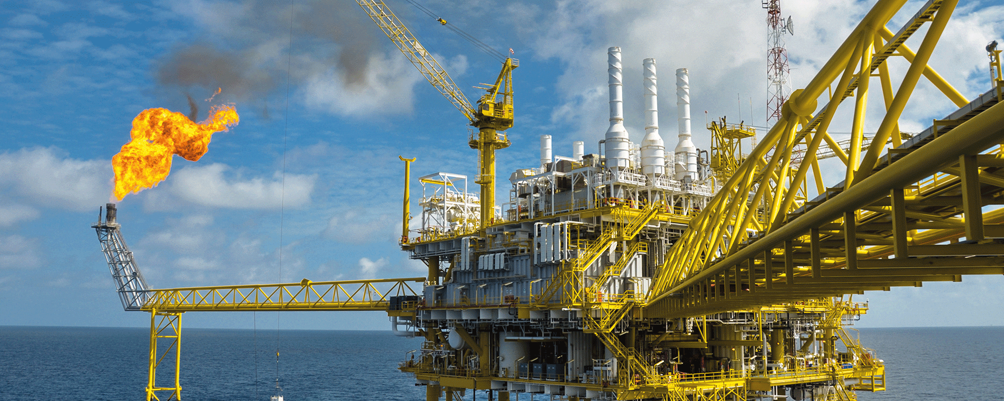
Onshore oil and gas assets are vast and usually cover a large area. These can refer to all upstream facilities i.e.facilities used for production and stabilisation of crude, or downstream facilities i.e., refining facilities. Upstream facilities can be divided into off-plot facilities e.g., wellheads, wellhead piping, flowlines, remote manifolds, trunklines/pipelines, and on-plot facilities e.g., stabilisation systems, separation/dehydrations systems, flare systems, produced water systems, utilities systems, storage facilities etc.
Typically, these assets are designed for a minimum of 25 years but in the real sense they are used for a longer period i.e., until total reservoir depletion or a halt in production due to global oil and gas economics. Thus, these assets need to be maintained consistently and occasionally optimised to aid production.
A Materials Integrity Assessment (MIA) is a multi-disciplinary review of materials and integrity of an operational asset with a view to mitigate failure or optimise production. This short article outlines the process for undertaking a MIA of an upstream facility.
A MIA can either be proactive or reactive in nature. These objectives are broadly categorised into the following:
To assess suitability of materials when a proposed brown field modification will introduce new production fluids/operating parameters to an existing facility.
To assess the material/integrity threats due to a change in the current operating conditions that can lead to a failure or loss of containment e.g., unexpected reservoir souring, sand production, oxygen ingress, build-up of microbial activity etc.
To proactively ensure the assets are operating within defined limits.
To proactively apply learnings from other facilities and global best practice.
The scope of an assessment can be the whole upstream facilities. or sections of the facility. This needs to be determined by the Client with the above objectives in mind. The scope will determine the duration of the project (from weeks to months) and the number of disciplines involved e.g., where only an on-plot scope is envisaged, there will be no requirement for a pipeline integrity engineer etc.
MIA Methodology
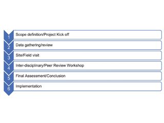
The methodology, and steps of the assessment are shown in figure1 below:
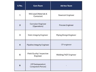
The scope/objective is defined by the Client in conjunction with the MIA Lead. The corresponding disciplines are defined, and personnel nominated.It is advisable to have a core team and an ad-hoc team on an on-call basis, a typical team comprises the disciplines shown below:
The ICP (Independent Competent Person) should be an experienced professional with no interest in the asset/facility who will be responsible to vet the assessment and to provide guidance where required. Individual and group roles and responsibilities are then defined with the expected time frame by the MIA Lead. It is critical to note the assumptions and exclusions at this stage of the project.Where there are known integrity concerns, these needs to be highlighted on a draft heat map displayed on a base PFS/PEFS drawings.The heat map tends to zero in on the areas that need special attention especially when undertaking a review of a very big asset. It also easily shows areas with similar integrity issues or failure patterns that will help with the assessment.
Data gathering and review is the most critical phase of a MIA.The data to be reviewed includes. but not limited to, the Facility Design Basis, Plant Operating Manual, Material Selection Reports, Corrosion Management Manuals, Inspection/Monitoring Data, CP Monitoring Data, Failure/Leak registers, Maintenance Plans/Reports, Trending Reservoir Data etc. Some well-organised and maintained facilities/assets will have this information readily available while others may have insufficient information.
Where the available data is insufficient, then several assumptions will need to be made. As an example, in a particular project where there was no baseline inspection data or any subsequent data after seven years of operation, the integrity assessment was then based on a greenfield (new) corrosion modelling. After going through the material selection process, this was then compared with what was physically on the ground and an evaluation made as to whether the right material selection had been made, and the expected remaining design life based on the existing process parameters. This comparison formed the basis of the subsequent recommendations.
A site/field visit is essential as it gives the team the opportunity to visually inspect piping, flowlines and equipment. It also serves as a verification process of the data provided or any of the identified integrity issues. The visit should also include interviews with key operation and inspection personnel who will be able to give their observations of any changes in the field and more clarity on the plant operations. Pre-prepared questionnaires are recommended for these interviews.
Interdisciplinary Peer Review Workshop
After the site/field visit, the team write up their findings based on the areas of responsibility allotted to each person. The whole write up is then discussed as a team to fine tune and align the findings. On completion of the interdisciplinary review, it is sent to the ICP who will then have a peer review with the whole team. This serves as a form of technical challenge of the whole exercise and the conclusions/ recommendations.
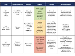
The report presentation should include a high-level summary using the traffic light system showing the overall status of the asset with the corresponding updated heat map. This high-level summary is based on a more detailed report of the individual areas. This report needs to include a full explanation i.e., scope/objective, overview/history of the asset, findings, where possible photographic evidence and recommendations. This should also be presented visually in a table. An example is shown (top of page 21) based on the earlier heat map.
Recommendations/Conclusions
The recommendations should list out action points to be carried out by the Client in order to verify the integrity of the onshore asset.These recommendations generally fall into the two categories outlined below:
Short term (less than 6 months) – These require urgent remedial actions/mitigation to avoid loss of containment of hydrocarbon inventory.
Long term (more than 6 months) – These require non urgent remedial actions to be undertaken over a course of time. Advisably between 6 months to 3 years depending on operational constraints.
The completion of the MIA is the presentation of the report (including a power point) to the Client.Any grey areas need to be clarified to the Client so the recommendations can be addressed within the given time frame.
A Corrosion Management Program (CMP) manual will include the process design and operating conditions, basis of materials selection, corrosion mitigation, inspection strategy as well as corrosion monitoring methodology. The manual needs also to include the risk assessment of critical assets to determine risk severity, monitoring techniques to ensure that the assets can be operated in a safe and reliable manner and the appropriate inspection methods to manage identified risks to maintain the integrity of the critical upstream surface facilities assets. It should also highlight the critical integrity operating window (IOW) parameters and IOW limits to be maintained during service. An IOW programme, its importance, and how to establish IOW to enhance asset integrity is discussed in detail in reference 2. The CMP manual needs to be revised at regular intervals to highlight recent inspection results, risk assessment data as well as changes in process conditions and additional monitoring requirements.
Corrosion monitoring as documented in a CMP manual can be conducted using a number of direct and indirect monitoring techniques, and the merits and limitations of each monitoring technique need to be considered. For effective corrosion monitoring multiple monitoring strategies need to be used and the collected data needs to be analysed along with appropriate process data.Details of various corrosion monitoring techniques for field applications can be found in the recently revised NACE publication (3). Installing coupons and corrosion monitoring probes can be useful tools for internal corrosion monitoring.These are considered intrusive monitoring types as they are exposed to pipeline interiors through appropriate access fittings. Proper safety precautions, following the work permit procedures, along with the deployment of suitably trained personnel are necessary for safe removal and installation of coupons from the pipelines during service.The NACE document “Preparation, Installation, Analysis and Interpretation of coupon data in oil field operations” serves as a useful guideline (4). Corrosion coupons are usually removed at 60-90 day intervals in order to establish long term corrosion rate trends, while the probes are useful to monitor the corrosion rates in real time. Suitable display of the probe’s output in the facility control room will enable the continuous monitoring of corrosion rates, and to alert the operating personnel in the event of higher corrosion rates in order for the required corrective action to be taken. Both wired and wireless configurations are available. The economics need to be taken into account before selecting suitable corrosion monitoring solutions. For pipelines requiring corrosion inhibitor injection, it is essential to have the probes/coupons installed upstream and downstream of the corrosion inhibitor injection point to monitor the performance of corrosion inhibitors. For reliable field corrosion data, it is essential to install the coupons at locations where corrosion is occurring, or most likely to occur, such as high velocity zones, water accumulation spots, etc. Careful location selection is vital since installing the monitoring devices at incorrect locations could obscure the data obtained and its analysis. Linear polarisation probes and electrical resistance probes are used for routine field corrosion intrusive monitoring of the process piping. Linear polarisation probes are commonly used in water systems, while electrical resistance probes can be used in higher resistivity environments. Formation of scales such as sulphide scale, sand erosion, oily/wax deposits at the sensor elements, can affect the accuracy of collected data. As a result, the collected data needs to be analysed carefully to establish a reliable base line reference for meaningful intrusive internal corrosion monitoring data.
In case of nonintrusive monitoring, probes such as thickness measuring sensors using ultrasonic principles can be installed at plant piping exteriors where continuous piping wall thickness monitoring due to corrosion/erosion is warranted, and a number of such systems are commercially available. These sensors can be installed at multiple locations and the wall thickness data, sensor battery life, and the temperature data, can be communicated in real time to the operating facility control room. The main advantage of nonintrusive monitoring is that the monitoring can be conducted when the plant is in service. In addition, critical piping at higher operating temperatures, and at elevated and inaccessible locations can be monitored.This approach offers cost-savings by eliminating the scaffolding requirements especially for elevated plant piping sections as well as avoiding the costs associated with the operating facility downtime to conduct the conventional thickness monitoring which would otherwise be required. By analysing the collected data, proactive corrective measures to mitigate piping corrosion along with scheduling the piping replacement in advance with the maintenance and operations team can be carried out. This approach enables the monitoring of the critical piping wall thickness condition to prevent the loss of containment due to internal corrosion thus facilitating the operation of the plant assets with highest safety and integrity, as well as to minimise HSE related events. As well as ultrasonic sensors, other methods such as eddy current testing, electromagnetic field mapping and battery free ultrasonic sensors are also considered nonintrusive monitoring types.
To manage critical upstream assets, microbiologically induced corrosion (MIC) also needs to be monitored and managed whenever applicable. Periodic process water sampling to monitor the planktonic bacterial counts, dissolved oxygen content, biocide residuals can be carried out. In oil and gas systems bio-film monitoring probes, samples from removed pipe sections, debris collected during pipelines scraping to monitor the sessile bacteria present in the system along with water quality parameters, provide good information (5).A number of test kits are commercially available to quickly monitor the biocide residual in the field and to initiate the required corrective actions. It is equally important to document the results and the implemented corrective actions to establish sound historical records.
To mitigate external corrosion threats, parameters such as periodic cathodic protection (CP) potential, current flowing in the structure, CP rectifier potential/current output levels, anode bed condition of underground assets, need to be monitored and managed within acceptable limits. Most of the underground carbon steel piping systems are usually protected by suitable protective coating systems supplemented by properly designed cathodic protection systems. Periodic visual monitoring needs to be carried out at excavated sections of pipelines to inspect the coating condition and to mitigate any external corrosion threats, and the monitored data along with inspection results should be documented.
When selecting the optimum corrosion monitoring solution from the wide range of available options for external and internal corrosion monitoring, the engineering and operational requirements and monitoring objectives, need to be considered, and thus by implementing a robust corrosion monitoring system combined with an effective data analysis, inspection and maintenance strategy, timely remedial measures, the critical upstream oil/gas assets’ integrity can be managed in an efficient and sustainable manner.
Dr. H.S. Srinivasan, Saudi Aramco
References:
(1) API RP 571-2020 Damage Mechanisms Affecting the Fixed Equipment in the Refining Industry.
(2)API RP 584-2014 Integrity Operating Windows.
(3) NACE TR3T199-2020 Techniques for Monitoring and Measuring Corrosion and Related Parameters in Field Applications, Houston, TX.
(4) NACE SP0775-2018 Preparation, Installation, Analysis and Interpretation of Corrosion Coupons in Oil field Operations, Houston TX.
(5) TM0194-2014-SG, Field Monitoring of Bacterial Growth in Oil and Gas Systems.
Protecting metallic structures from corrosive attack is not just about using coatings or cathodic protection, the design of the structure also plays an important part. There maybe situations which call for two different metals, or alloys, to be joined. If these metals are electrically connected under conditions permitting the formation of a “corrosion battery”, then in this situation, one metal can corrode preferentially in relation to the other metal to which it is physically and electrically connected. This is termed “galvanic corrosion”.
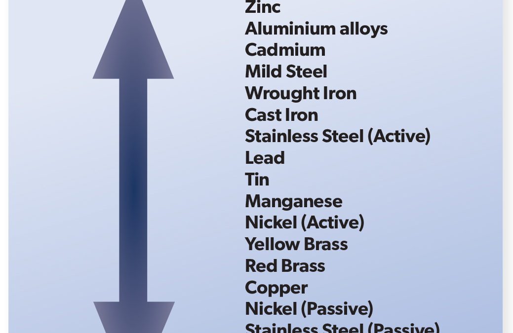
Galvanic corrosion is an extremely important corrosion process, and one that is frequently encountered. The principles of galvanic corrosion are used to advantage in the cathodic protection of surfaces by using sacrificial metal anodes or inorganic protective coatings. The Galvanic Series lists the activity of metals in order, from the most active (magnesium) to the least active (platinum). When two metals are connected, the metal located higher up the scale will corrode preferentially, and thereby protect the metal lower down the scale from corrosion attack. As an example, if copper and zinc are connected together, the zinc will dissolve, or be corroded preferentially, thus protecting the copper. The metal attacked is defined as the anode, thus the zinc will serve as an anodic area, and the copper will form the cathodic, or the protected area. The function of each will be identical to that found in the typical corrosion cell, as in the set up for rusting of iron. The intensity with which the two metals react in this preferential manner can be measured by the distance between the two metals in the Galvanic Scale. As magnesium is at the top of the scale it will have a tendency to corrode in preference to any other metal shown on the Galvanic Scale, conversely, platinum, which is extremely inert, never corrodes preferentially. While the tendency to corrode depends on the kinds of metal coupled together, the rate at which the corroding anode is attacked depends on the relative area of the anodes and cathodes joined together.
If a small magnesium anode is coupled to a large area of steel (as in protection of a ship’s hull), the anode area (being small as compared to the cathode area) will corrode very rapidly. This is due to the entire galvanic current being concentrated on a small area of active metal. Conversely, if the cathode area is small compared to the anode area the corrosion of the anode will be relatively slow, since the demand on the anode is spread evenly across the whole surface of the metal. It must be kept in mind that the areas of each metal involved are those in electrical contact and not just the areas of metal in physical contact. The area of metals in electrical contact will be determined by those areas which are in contact with an external conductive circuit (electrolyte).
For example, in the use of rivets of one metal to fasten together plates of different metal, we find an excellent example of possible effects of galvanic corrosion. If steel plates (anodes) were joined with copper rivets (cathodes) only a very slow corrosion of steel would occur, since the galvanic corrosive effect is spread out over a large area of steel. On the other hand, if copper plates (cathodes) were joined with steel rivets (anodes), a rapid rusting of the rivets would occur. The small area of rivets would be attacked by all the galvanic current generated by large copper plates and would corrode rapidly.
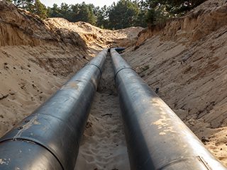
Buried metallic structures are common in the oil and gas, petrochemical, and chemical industries. These structures are exposed to a corrosive underground environment which results in their degradation and eventual failure in the form of loss of primary containment. The preferred fabrication materials for the construction of buried assets are carbon and low-alloy steels. Carbon and low alloy steels with some means of mitigation have low capital and operating cost (Opex and Capex) over the asset life cycle when compared to other engineering materials (e.g., polymeric and corrosion resistant alloys). Other notable reasons are, better environment management, safety and security concerns, and long-term strategic objectives. Whilst most buried assets are made of carbon and low-alloy steels with some means of external corrosion control (e.g., protective coating and cathodic protection system), in specific cases where historic data indicate severe corrosion that cannot be acceptably reduced with some means of mitigation in the exposed environment, the other option is to utilise stainless steel or other corrosion resistant alloys (CRA) to reduce corrosion to as low as reasonably practicable. Despite of the superiority of stainless steel to carbon steel in terms of its resistance to corrosion and environmental assisted cracking, it is not immune to localised corrosion damage in the form of pitting, crevice corrosion, stress corrosion cracking (SCC) and intergranular corrosion. Hence, when CRAs are used, there is a need for monitoring, mitigation and management to achieve asset design life during its operation.
Buried metallic assets are exposed to soil, atmospheric gases, ground water and corrosion activating bacteria such as sulphate reducing bacteria (SRB), and others. External corrosion of buried assets is directly influenced by oxygen as it promotes the cathodic reaction, other parameters that accelerate external corrosion are, soil type (e.g., clay, marshy etc.), pH, presence of chlorides, stray current, and induced alternating current. Stray currents can be direct current from a cathodic protection system (CP) or alternating current, e.g., from powered transit systems, electrical welding operations, and mining operations. Also, buried metallic structures that are less than 500 m from power lines rated at 312kV and above, are at risk from induced ac corrosion, plus pose an induced ac hazard to maintenance personnel, and an adverse effect on the cathodic protection system. Although, industry statistics for buried metallic structure show that failures due to induced ac are rare, best engineering practice and codes (e.g., NACE SP 0169, 2013; NACE SP0285, 2011 and API RP 1632, 1996) recommend effective mitigation based on powerline rating, separation distance. angle of overhead, soil resistivity, coating conductance, type of powerline support pole (e.g., metal/wood etc.), and other factors. It is best to carry out computer modelling to assess the effect of ac interference on a buried structure prior to implementing mitigation measures. Due to the complex variables that influence corrosion of buried metallic structures, atmospheric, soil, microbiological influenced corrosion (MIC), and stress corrosion cracking (SCC) are all possible.
The corrosion rates in different soil types vary with soil chemistry, mineralogy and permeability. Soils with poor drainage like clay are more corrosive than soils with excellent drainage like sand. Soil contains base and acid forming elements. Base forming metals that influence corrosion are sodium, calcium, potassium, and magnesium. Acid formers are chloride, carbonate, nitrate, sulphate and bicarbonate. Chloride ion concentration in water can be determined using the ASTM D 512-12 method (withdrawn 2021) and sulphate ion concentration in water is determined using ASTM D516-16 (2016).
The electrical resistivity of the soil greatly influences corrosion, as resistivity increases, the conductivity decreases, and vice versa. Soil resistivity less than 1000 ohm-cm is severely corrosive, and resistivity greater than 10,000 ohm-cm is considered progressively less corrosive. The ASTM G 57-20 (2020), method is recommended, using the
Four-Pin method or the Soil Box (Nelson meter), for determination of soil resistivity, and for greater depths, the Geonic EM 37 can be used.
Soil pH influences soil corrosivity. At a pH value less than 4, the soil is extremely corrosive to carbon steel and at a value greater than 10 soil corrosion is controlled except in the presence of strong alkaline solutions. Field operating data for carbon steel, indicates it is unaffected by pH except at a value less than 4, or greater than 10, with the cathodic reaction driven by oxygen reduction. As the moisture content reduces, even at higher soluble ion concentration (very dry soil), the soil corrosivity reduces.
At the pH range found in most soil, oxygen would usually be present for corrosion to take place. This is because most soils have either a neutral or slightly alkaline pH which does not accelerate corrosion except when there is poor aeration or differences in oxygen concentration in the soil creating an anaerobic condition that promotes galvanic (differential concentration) corrosion cells.
Sulphate reducing bacteria (desulfovibrio desulfuricans) can be found in soil with anerobic conditions containing organic matter like clay soil. This results in MIC of metallic structures. Details on the characteristics of soil can be found in ASTM STP 1013. For a better understanding of soil corrosion behaviour, it is advisable to collect soil samples at the installation depth for a detailed soil analysis prior to installation of asset.
The predominant damage modes for buried metallic structures are progressively, wall thinning, pitting and cracking. Common failure modes are pin hole leak, small to moderate leak, large leak, rupture and fracture. Because of the adverse effect on people, environment, asset, and company reputation in the event of loss of primary containment, the integrity of buried assets should be considered a priority.
To ensure effective mitigation of external corrosion, during backfill the soil should be carefully selected to ensure it is dry and free from gravel, clay, rocks, marshy soil, and other harmful corrosion activating materials. The buried structure should be coated with a protective coating (often high build epoxy, vinyl ester etc.) and inspected at hold points to ensure conformance to specification. The coating should have high dielectric strength, superior resistance to water ingress, good mechanical properties (adhesion and abrasion resistance), good flexibility, compatible with CP, withstand degradation due bacteria, excellent performance, long service life, and ideally have low application cost. The asset should also be protected with impressed current CP or sacrificial anode CP with a design life greater than that of the structure.
A CP interference survey should also be conducted to rule out stray current, and if found, should be mitigated to prevent sudden loss of containment.Company standards and codes should be enforced during the engineering, procurement, construction, installation, pre-commissioning and commissioning phases of any buried metallic asset. Because of the criticality of buried assets, it is vital to develop and implement an integrity management programme that is risk-based (API 580, 2016). For pipelines, a risk-based assessment (RBA) should be conducted to determine the remaining asset life. Finally, I would advise the use of ISO 55000 (2014) and 9001 (2015) to develop the asset management plan to increase top leadership commitment to integrity whilst ensuring continual improvement. Joseph Itodo Emmanuel, Consultant, Joiegloe Global Synergy
In this issue, we have three articles from experienced Fellows who have made a significant contribution to the understanding of corrosion and its prevention. The first follows on from the topic in the last issue, where Brenda Peters discusses the application of protective coatings, and what needs to be done beforehand.Secondly, Joseph Itodo Emmanuel describes the corrosion protection of buried structures, and finally James McLaurin explains how the design of a steel structure can influence its protection, specifically from bi-metallic corrosion problems.
Corrosion protection by protective coatings
The institute of Corrosion is split about 50:50 between Engineers and Scientists, and across several different disciplines, the common ground is in Corrosion Prevention, and there are many overlaps within the fields of expertise.Following on from the Fellow’s Corner column in last issue of Corrosion Management, the emphasis of this article is on paint as a means of corrosion protection.Paints generally falls into two categories, decorative and industrial (protective), and paint manufacturers have tended to split their manufacturing and R&D, specialising in one or the other. However, decorative paint can be protective and industrial paint can be decorative. When we talk about “Industrial” or protective paints, we are usually referring to the prevention of steel from rusting. These paints are the most sophisticated technically engineered paints, but they tend to be applied by the least qualified painters. This is why the Correx ICATS (Industrial Coating Applicator Training Scheme) programme was developed to improve the quality and longevity of the finished product.In addition, many manufacturers will run their own training schemes on how their particular product should be mixed and applied and the limitations of the ambient conditions. Paint inspectors are also employed to ensure that the paint is stored and applied correctly, and the surface preparation is to the specified standard. These paint inspectors are normally trained by ICorr or NACE or both, so what can go wrong?
When applying paint to new steel a primer coat is applied to promote adhesion and protect the surface against corrosion, however preparation of the steel prior to painting is paramount. When investigating paint failure, it is a bit “chicken and egg”, did the steel corrode and push off the paint or did the paint fail allowing the steel to corrode.
When the steel leaves the mill, it will have some level of millscale on the surface which is blue/black in colour, although this surface can look nice and smooth and suitable for painting, this millscale is however only loosely adhered to the underlying steel, and will scale off after painting.This can often be seen on hand rails and post made from tubular steel which has not been blast cleaned.
To prepare steel for painting, several methods can be used, which depend to an extent on the end use of the material,for example, steel can be pre-treated to inhibit rust and passivate the surface: examples of which are in hot dip galvanising, where the steel is “pickled” in acid to remove rust and millscale then immersed in a vat of molten zinc, which forms layers of zinc alloys at the interface with the steel, culminating in a layer of pure zinc on the surface, and this can be difficult to paint as it is smooth and can result in poor adhesion. It can be left to weather so that zinc oxides form on the surface resulting in roughening which provides a key for the paint to adhere to, or alternatively a variety of primers are available which etch into the surface. These include, acid etch epoxy primers and more the commonly used “T Wash”, a mordant solution originally developed by British Rail, which is a phosphoric acid solution containing alcohol and copper carbonate as an indicator. The solution reacts with the surface of the zinc and a black coloration is formed, anywhere it doesn’t react and show this colour change can indicate previous contamination on the galvanising and these areas need to be washed, degreased and retreated.
Steel can be treated with hot metal spray (Thermal Spray) as an alternative to hot dip galvanising creating an anti-corrosive layer with a profiled surface to which paint can be applied. This is normally zinc or aluminium and is often used for high temperature conditions.
Similarly, steel can be “phosphated” by dipping in a bath containing a solution of zinc in phosphoric acid forming a thin layer of zinc phosphate on the surface, and which is commonly used in the automotive industry. This can then be undercoated and a decorative finish coat applied on top. The paint can be applied electrostatically in a powder or liquid form then heat cured or applied by spray, roller or brush.
However, in the heavy duty protective coatings field, steel supplied from the factory has to be blast cleaned to remove all millscale and rust, and then primed within a short period of time to prevent flash rusting from forming on the surface. Epoxy primers are commonly used, but these need a good steel surface profile to form a key to ensure good adhesion, so the profile of the blasted steel needs to be checked before application of the paint.As epoxies cure by chemical reaction, they will continue to cure over time until they become fully cross linked, and at this stage they become unsuitable for overcoating, so the manufacturers’ overcoating times must be adhered to enable the following coats to adequately bond with the surface of the epoxy. If the overcoating time is exceeded, these coats will eventually lose adhesion at the interface with the epoxy, and detach. Epoxies, like most protective coatings, are also sensitive to ambient conditions, they won’t normally cure if it is too cold, and if there is any condensation on the steel, or if they get wet before they cure can prevent them from curing properly. For example, with amine cured epoxies, the amine can react preferentially with moisture resulting in undercure, and if moisture gets on the surface before they
are fully cured, amine bloom can occur resulting a dull and chalky surface. Therefore, attention to temperature and dewpoint are very important. Epoxy coatings have been developed which are moisture tolerant and some can even be applied underwater and are utilised for subsea repairs.
When epoxy primers are used then these need to be finished with a decorative acrylic or polyurethane top coat as these are UV resistant – epoxies yellow with sunlight and colours fade through chalking. Acrylics retain their colour longer.Similarly, for alkyd based systems, urethane alkyd top coats are used as these are tougher and have greater longevity.
Historically red lead primers were used, although these were phased out in the late 1960s due to toxicity and leaching they can still be found on many steel structures, and cause problems when it comes to maintenance (full containment and special disposal are necessary).These have been replaced by zinc rich or other anticorrosive primers.
Similarly, some steel structures have existing coats of chlororubber or acrylated rubber, which have good corrosion resistance and longevity.However, these can also pose problems during maintenance painting, as they are incompatible with solvent based coating like epoxies, and cannot be refurbished with anything else.
Whichever paint system is chosen it is advisable to use material supplied by the same manufacturer as these are developed to be compatible with each other, and if a failure should occur then there is less anomalies to be considered.Manufacturers will offer a full paint system with primers undercoats and finish coats, for a specific end use. Brenda Peters
In this series of articles by practitioners who have made a significant contribution to the field of corrosion protection, the editor discusses paint technology.
Over the past 18 months this column has concentrated on topics relevant to the corrosion engineers, however, there is a need to address the part that protective coatings play in the corrosion protection of structures.In an attempt to address this imbalance, this issue will feature an introduction to paint technology, and how protective coatings fit into the overall corrosion protection scenario.
Paints and coatings are used to protect and decorate, however, before we consider the properties of paints and how they work, it is necessary to consider “what is a paint”.
All liquid paints are composed of three basic ingredients, resins, pigments and solvent. The resin is the film forming portion of the paint – it holds together the pigment particles and binds the paint to the surface. The resin plays the main part in contributing to the durability, strength and chemical resistance of the final film.Paint types are often referred to by the type of resin in the formulation, so when we talk about an alkyd or epoxy for example, we are referring to the main resin used to make the paint.
The second ingredient in a paint is the pigment. This is a relatively insoluble finely divided powder, or more commonly a mixture of powders. The pigment(s) primarily provide hiding power (opacity), and colour, but they also improve corrosion and weathering resistance, increase paint adhesion, decrease moisture permeability and control gloss. The final ingredient, the solvent, “carries” the resin and pigment(s) and controls the viscosity, such that the paint can be applied to a surface. The chemical ingredients in each of the components vary widely from one generic type of paint to another, in addition each of the components (resin, pigment and solvent) are also usually mixtures of different materials. For example, a paint formulation may contain three or four solvents – one solvent dissolves the resin, while some are used to control evaporation, and others are used to dilute the solution (control viscosity). It is not important for a user to know all the ingredients in a paint, suffice that he knows the properties.
The words, paint and coating, are used interchangeably – they mean virtually the same thing. However, it is necessary to distinguish between a coating system and a coat of paint. A coating system is more than just the material applied, it also refers to other factors such as the surface preparation requirements, the application of a number of coats of paint, in a specific order, and the thickness of each coat of paint. A coat of paint is a single layer, applied to form a coherent film when dry.
The common designation of a series of coatings applied to a surface is primer, intermediate or build coat, and top coat. Normally each coat contains properties that contribute to the success of the total coating system.
Function of each coat
The primer is the first coat applied to the surface. The main function of the primer is to provide adhesion to the substrate – if the primer doesn’t stick, then the whole coating system will fail. The primer also provides a key for the rest of the system.
The intermediate coat is required in many coating systems to provide one or more of the following functions; increase film build, improve chemical resistance, or serve as an adhesion or tie-coat between primer and topcoat where they are not compatible.
The topcoat is intended to be the last coat applied. This provides the weather and/or chemical resistance and also imparts characteristics such as colour, gloss wear resistance, abrasion resistance.
Considering the two main reasons for painting – protection and decoration, this article will concentrate on the protection properties.A paint can protect against, amongst others, abrasion, chemicals and fire, but probably the most common protection use is to prevent corrosion of steel.
There are three recognised ways that coatings protect steel against corrosion, providing a barrier, inhibition and sacrificial action.
Barrier protection is just as the name implies, the dried paint film blocks moisture from reaching the steel surface. All coatings do allow moisture and oxygen to penetrate them to some extent, this is called permeability. Coatings which protect by a barrier mechanism have very low permeability. Typical barrier coatings are 2-pack epoxies and polyurethanes, although there are additives which can reduce permeability further (see below).
Coatings that protect by inhibition contain active pigments to inhibit or interfere with the corrosion reaction on the steel surface. Typical traditional inhibitive pigments were lead compounds and chromates.However, concerns about toxicity and environmental pollution have led to their replacement with so called non-toxic anticorrosion pigments such as phosphates, and many proprietary materials. As moisture passes through the film, the anti-corrosive pigments slowly dissolve and depending on their chemistry interfere with either the anodic or cathodic reaction and thus retard corrosion.
The third mechanism is sacrificial action and is the way that zinc rich primers protect steel.These primers are highly loaded with zinc, such that the zinc is in contact with itself and the steel surface.As zinc is more active than steel, and if the elements necessary for corrosion are present, then the zinc will corrode in preference to the steel (i.e. sacrifice itself), and hence protect the steel. Zinc rich paints are classified into two types, inorganic and organic. This classification refers to the resins used in the formulation and not the form of the zinc.The binder (resin) in inorganic zinc rich coatings is a form of silicate, and organic zinc rich paints are nowadays typically epoxy based.
Returning now to the paint system. This is designed to give optimum protection to the steel or metal substrate by combining the properties of the various coats. Thus for very long term protection, an inhibitive primer, or more particularly a zinc rich primer, would be combined with a barrier intermediate coat and topcoat.In this way, two protective mechanisms are used to give long life protection.
The permeability of a paint and hence its barrier properties are related to the resin used, with oleoresinous and alkyd paints having high permeability and epoxy and polyurethanes having lower permeability due to their highly cross-linked structure.Within each generic class of paint, permeability can be further reduced by formulation, and in particular the use of plate-like pigments such as micaceous iron oxide (MIO) and aluminium flakes. These special pigments orientate themselves parallel to the surface when the paint dries and provide an extremely low permeability film (they effectively increase the path length moisture has to take to reach the metal surface). In a similar manner, permeability can be reduced by increasing film thickness although there is a limit to this before other properties start to suffer.
No matter which type of paint is used, if proper surface preparation is not carried out then vastly inferior performance will be obtained.Surface preparation is essential in two important areas, it provides an anchor for the coating and it allows intimate contact between the coating molecules and the metal surface, and this will be the topic
for a future column.
Non-metallic materials are an essential element of facilities engineering in upstream E&P operations, being widely used in a range of functions from seals and corrosion barriers to piping and structural elements. This short article offers a brief insight into the capabilities of some of the available options.
In common with metallic materials, the selection and successful use of non-metallics is dependent on a detailed understanding of the way in which each material responds to the service environment over the life of the component, or system. Degradation of the capabilities of non-metallic materials can occur through a range of physical and chemical processes.
Elastomers (or rubbers), are widely used in oilfield sealing applications. These are highly elastic, polymeric materials, used in compression seals in a range of downhole, subsea, topsides and pipeline applications. Various nitrile and fluorocarbon-based materials are typically used to span the range of temperatures, pressures and fluid environments, met in oilfield operations. Processing of these materials involves “vulcanisation” or curing, using small amounts of sulphur, amines or peroxides to create highly flexible and extendable polymers.
A number of key failure modes can affect elastomer seals.Some relate to the elastomer material being used outside its working temperature range, or in fluids with which it is incompatible. This can lead to chemical embrittlement, softening, compression set, large volume changes, and loss of elasticity at low temperature – any or all of which can lead to a seal failing. Pressure related failure modes can also be important. Extrusion damage occurs when a rubber seal is forced into the gap which it is sealing as a result of the applied pressure. Gas decompression damage occurs primarily in dry gas duty, being qualitatively similar to the “Bends” suffered by divers when returning to surface.
Qualification of seals and the material’s performance in any component or system, is typically carried out using a combination of materials and system testing, taking account of the time and temperature dependent properties of the materials involved. Finite element analysis (FEA) modelling of the complex, non-linear and time dependent materials properties of elastomers has proven vital in understanding some applications.
Further applications of a range of elastomer materials are to be found in hydraulic and transfer hoses, and in the flexible joints that are incorporated in metal drilling and catenary risers.
Thermoplastic materials, such as polyethene and nylon, find wide application in controlling the internal corrosion of steel pipelines. Such materials are fundamentally different in nature to elastomers, having a much smaller elastic range, and the way in which they are used is therefore somewhat different. As their name suggests, these materials are reversibly melt-processible, often being formed by extrusion for oilfield use. Materials are typically differentiated by their maximum service temperature capabilities, and their resistance to particular service fluids. So, for example, polyethylenes are typically used in water duties to a maximum of 60°C or so, while nylons can be used in hydrocarbon production service up to 90°C.
Thermoplastic liners have an extensive track record, both onshore and offshore, in providing a corrosion barrier within carbon steel pipelines, particularly for water injection service, where suitable metallic options are typically much more expensive or much less reliable. There are a number of “pull-through” liner technologies which can offer cost effective solutions to mitigate internal corrosion challenges in both new build projects and in rehabilitation. Often these involve “tight-fit” polyethylene liners, which have their outer diameter mechanically reduced, while they are pulled into a steel pipe. Release of the pulling force allows the polymer to relax back against the internal diameter of the pipe, which remains the structural element of the pipeline. Another option is the use so-called Reinforced Thermoplastic Pipes (RTPs) which are used, with good economic benefit, as loose fit, “slip liners” or even as stand-alone pipelines, in a range of production and injection services. These are composites in which glass, aramid or carbon fibre, or wire, reinforcement, is wound over a plastic pipe, in order to increase its pressure capability.
Thermoplastic materials additionally find wide application in unbonded flexible pipes, importantly being used as the internal and external sheathes in these complex pipe structures. The flexibility of these pipes often enables faster or more convenient offshore installation and hook-up, and provides excellent fatigue resistance in a range of harsh environments. Several thermoplastic materials are used as internal pressure sheathes, responsible for primary containment. Nylon materials are widely used in production service up to 60 – 90°C, with fluoropolymers used at high temperature, to around 130°C. In water injection, polyethylene is normally used. External, or outer, plastic sheathes contain the whole pipe structure, helping to keep the high strength steel wire reinforcement out of contact with seawater. Typically, this sheath is made of polyethylene for static pipes and nylon for pipes used in dynamic service.
Thermosetting materials, such as epoxy and phenolic resins, form the basis of a further set of related oilfield corrosion protection technologies. These materials employ a chemical hardener to permanently, and irreversibly, “set” the polymeric resin, often with temperature applied during curing to accelerate that reaction.
Fusion bonded epoxy (FBE) is used very widely as an external pipeline coating. It is applied as a powder to a carefully prepared surface, and melted and cured in situ to give a coating approximately 0.5 mm thick.
FBE also finds wide use as the base layer in multilayer coatings with polyethylene and polypropylene. Further, options for subsea insulation involving the incorporation of glass microspheres into thermoplastic layers are also widely accepted, for use on subsea pipelines. The thermoplastic nature of these materials allows the pipelines to be reeled for transport and installation, where required. Where more rigid insulation is acceptable, systems incorporating glass-microspheres into epoxy resins can be applied, for example to subsea manifolds.
Epoxy resins, and similar materials such as vinyl esters, find wide use in the painting and external protection of structures and equipment, as well as in the internal coating of vessels, typically in combination with glass flake fillers.
Glass reinforced epoxy pipes find a range of downhole, piping and pipeline applications, mostly in water service. Typically, this kind of pipe is rated to 16 bar design pressure, although some small diameter products can go much higher than this, for example in downhole tubing applications. A range of adhesively bonded, mechanically jointed and threaded connections are used across the industry. Qualification of composite pipes, and other non-metallic pipe options, is normally undertaken through a series of full-scale pipe tests, including: pressure rating using long term (10,000 hr) testing of pipe and end fittings, characterisation of minimum bend radius for storage, transportation and operation, characterisation of axial load capability, testing of capability of the product to handle gas service, and performance of the product in UV. A range of other engineering design issues also need to be worked through with each product, such as internal surface roughness, heat transfer co-efficient, and pipe expansion due to pressure and temperature.
Glass reinforced epoxy pipes can also be used as a liner, with composite lined downhole tubing having a long track record of successful onshore use in a range of corrosive services, and in offshore water injection. Some composite liners are capable of continuous service at up to 80°C in water-based applications. Insertion of the stiff liner into the steel host, on a joint-by-joint basis, leaves a small annulus between the liner and the host which is typically filled with cement, to transfer mechanical and pressure loads to the carbon steel host. Modified tubing connections allow the liner to be properly terminated, with thermoplastic corrosion barriers providing continuity of corrosion performance.
Finally, it is worth mentioning the use of external epoxy composite wraps to repair and reinforce topsides piping. This is a very convenient repair technology that does not involve hot work and which can be used to seal thinned, cracked or holed piping, at very least as a temporary solution until full repair can be affected.
The use of non-metallic components is an integral part of the materials selection challenge in oil & gas production. Given their frequent role in maintaining a primary or secondary containment, selection and use of these materials should be as carefully scrutinised as with the metallic components within any well, processing facility or pipeline.
For additional information see,B Kermani and D Harrop, Corrosion and Materials in Hydrocarbon Production; A Compendium of Operational and Engineering Aspects, Wiley, 2019, Chapters 9 & 15.
We use cookies to optimize our website and our service.
Functional
Always active
The technical storage or access is strictly necessary for the legitimate purpose of enabling the use of a specific service explicitly requested by the subscriber or user, or for the sole purpose of carrying out the transmission of a communication over an electronic communications network.
Preferences
The technical storage or access is necessary for the legitimate purpose of storing preferences that are not requested by the subscriber or user.
Statistics
The technical storage or access that is used exclusively for statistical purposes.The technical storage or access that is used exclusively for anonymous statistical purposes. Without a subpoena, voluntary compliance on the part of your Internet Service Provider, or additional records from a third party, information stored or retrieved for this purpose alone cannot usually be used to identify you.
Marketing
The technical storage or access is required to create user profiles to send advertising, or to track the user on a website or across several websites for similar marketing purposes.