

PFP – An Introduction to Intumescent Coatings

PFP – An Introduction to Intumescent Coatings

The Role of Intumescent Coatings in Passive Fire Protection

Intumescent coatings have been a key strategy in the protection of buildings and other structures against fire for several decades. They form part of a passive fire protection strategy that might also include other materials such as concrete, mineral fibre boards, vermiculite, and cements.

In this article, we explore the effectiveness of intumescent coatings in providing passive fire protection for diverse types of structure, including offshore platforms and commercial buildings.

What Is Passive Fire Protection?

Fire protection in buildings and structures is crucial for safeguarding lives by delaying structural collapse which allows enough time for safe evacuation. It does this by either preventing fire or delaying the escalation of fire.

Active fire protection provides an immediate response to either suppress or extinguish a fire. Key components include fire alarms systems; sprinklers; suppression systems (such as foam and dry chemical systems); smoke control systems; and emergency lighting.

Passive fire protection (PFP) helps to prevent, withstand, and contain fire within a structure. These measures are integrated into the structure, and designed to protect the structural integrity of the building and provide occupants with sufficient time to evacuate safely. Key components of PFP include fire resistant materials; compartmentation (division of a building to contain the spread of fire and smoke using tactics like fire walls, fire doors, and fire-rated partitions); firestopping sealants; fire resistant insulation and intumescent coatings.

A Brief History of the Use of Intumescent Coatings

Intumescent coatings have been integral in protecting steel structures from fire for about 40 years. When exposed to fire, these coatings swell to create a protective barrier that can last up to four hours, significantly delaying the steel from reaching its critical failure temperature of approximately 400°C.

In the 1980s, the use of intumescent coatings saw a significant rise in Europe. Major oil companies recognised their ability to protect structural steel from the intense heat of hydrocarbon fires. This period also saw an increase in the use of exposed steel in commercial and high-rise buildings, which further boosted the demand for aesthetically pleasing, but simultaneously safe, coatings.

How Do Intumescent Coatings Work?

The chemistry of intumescent coatings involves several components:

  • An organic binder resin (epoxy for hydrocarbon fires or acrylic for cellulosic fires)
  • An acid catalyst (such as ammonium polyphosphate)
  • A carbonific source (like pentaerythritol), and a spumific agent (e.g., melamine)

Upon exposure to fire, these ingredients react to form a low thermal conductivity carbon char that expands to provide a protective barrier. This char layer insulates the steel, reducing heat transfer and extending the time before the steel reaches its critical failure temperature.

Types of Intumescent Coatings

Intumescent coatings are categorised as thin-film or thick-film:

  • Thin-film intumescents, often single-component solvent or water-based products which have dry film thicknesses (DFTs) of less than 5 millimetres.
  • Thick-film coatings are typically solvent-free and epoxy-based which have DFTs up to 25 millimetres.

Recent advances have introduced multi-component methacrylate or ‘hybrid’ products, providing specific advantages over traditional formulations.

Which Type of Intumescent Coating Should Be Used?

Thin-film intumescents are typically used for aesthetic applications in commercial buildings, providing a paint-like finish. In contrast, thick-film coatings are used in more industrial settings, offering robust protection.

To specify the correct intumescent coating, it is essential to identify the item to be protected, such as structural steel or fire-resistant bulkheads.

The coating thickness depends on the steel’s weight and type, with lighter sections requiring thicker coatings for adequate protection. Determining the appropriate coating thickness involves calculating the steel’s shape and considering any irregularities. Manufacturers provide guidance for this and third-party certification ensures compliance with standards, ensuring optimal protection.

Common Applications for Intumescent Coatings

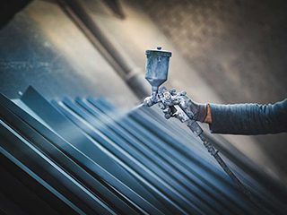
Intumescent coatings can be applied using various methods, including spraying. New hybrid products have expanded application possibilities, offering enhanced performance and flexibility. Typical situations in which intumescent coatings are used include:

·       Commercial and Residential Buildings

Intumescent coatings are widely used in commercial and high-rise buildings to protect exposed steel, blending safety with architectural aesthetics.

·       Industrial Facilities

In industrial settings, especially offshore platforms and floating facilities, intumescent coatings protect structural steel from the extreme heat of hydrocarbon fires, ensuring the integrity of critical infrastructure.

·       Transportation and Marine Industries

These coatings are also used in transportation and marine industries, protecting against cellulosic and hydrocarbon fires, including jet fires resulting from high-pressure fuel releases.

Testing Intumescent Coatings

Given the variability in fire conditions, standardised tests offer a reproducible method to evaluate coating performance, ensuring reliability under different scenarios.

Intumescent coatings are subjected to standardised fire tests to ensure their effectiveness. Standards like BS 476 and EN 13381 for cellulosic fires, and UL 1709 and ISO 22899-1 for hydrocarbon fires, provide benchmarks for performance.

Further, to provide effective fire protection, intumescent coatings must be durable and intact when exposed to fire. Therefore, formulating these coatings requires careful consideration of moisture sensitivity and environmental resistance to prevent corrosion and ensure long-term protection.

Different resins are used based on the application environment. For example, water-based acrylics are suitable for dry, internal locations, while solvent-based epoxies are used for more demanding conditions. Standard tests like NORSOK M 501 and UL 2431 ensure these coatings meet durability requirements.

ICorr’s Passive Fire Protection Courses

To enhance understanding and application of passive fire protection, the Institute of Corrosion (ICorr) offers specialised Passive Fire Protection (PFP) courses. These courses provide in-depth knowledge on the principles of PFP, including the selection and application of intumescent coatings. Participants learn about the latest standards, testing methods, and best practices in ensuring the durability and effectiveness of PFP systems.

For example, the PFP Coating Inspector (Epoxy) Level 2 trains and examines Inspectors of Epoxy Intumescent Passive Fire Protection on the inspection of common types of epoxy coatings used to protect against hydrocarbon fires on installations for both on and offshore facilities.

ICorr’s courses are designed for professionals involved in fire safety and providepractical insights and certification to ensure the highest standards of fire protection in various industries.

Intumescent Coatings: The Bottom Line

Intumescent coatings provide critical passive fire protection, offering up to four hours of defence against fire. Applications range from commercial buildings to industrial facilities, ensuring safety and structural integrity across various environments. With advances in formulation and application techniques, intumescent coatings continue to evolve, enhancing fire protection capabilities in diverse settings.


Designing, Monitoring, and Integrating Cathodic Protection with Coatings

Designing, Monitoring, and Integrating Cathodic Protection with Coatings

Key Knowledge to Ensure Longevity of CP Systems

In the first two articles in this mini-series, we explored the basics of corrosive reaction and using cathodic protection to counteract the corrosive reaction. In this third and final instalment we cover the design, monitoring, and maintenance of CP systems and their interaction with protective coatings. Understanding these aspects is essential to ensure the long-term effectiveness and reliability of CP in preventing corrosion.

Design of Cathodic Protection Systems

Designing an effective CP system requires a detailed assessment by a cathodic protection engineer.

The engineer must determine the need for corrosion protection, decide on the appropriate CP system, and calculate the current requirement and optimal locations for anodes. The goal is to ensure that the CP current is uniformly distributed to protect all intended surfaces and to achieve the most economical and reliable solution.

In complex structures, mathematical modelling may be employed to optimise anode locations, spacings, and sizes.

Monitoring and Maintenance of CP Systems

Regular monitoring, and maintenance are crucial to the performance of CP systems. All anodes, whether galvanic or impressed current, degrade over time and need to be replaced periodically. CP systems can be designed to last up to 50 years, but this requires routine inspections and potential adjustments to ensure continued effectiveness.

Monitoring involves measuring the steel/electrolyte potential using fixed monitoring locations or portable survey equipment. This data helps the CP engineer determine if the current delivery and distribution are adequate, optimal, or need adjustment. Ensuring proper CP performance involves maintaining the balance between current density and distribution to prevent corrosion effectively.

Interaction of CP with Protective Coatings

CP is often used in conjunction with protective coatings to provide enhanced corrosion protection:

  • The coatings act as a barrier, reducing the overall current demand of the CP system and improving current distribution by isolating the metal from the corrosive environment.
  • CP then protects the steel at damaged areas of the coating where the underlying metal is exposed.

Not all coating systems are suitable for use with CP:

  • Coatings must be compatible with CP operation and withstand cathodic reactions, which can generate alkaline conditions.
  • Coatings used with CP should undergo ‘cathodic disbondment’ testing to ensure they are not damaged by these reactions.
  • Additionally, excellent adhesion to the metal surface is crucial to prevent disbonded coatings from shielding the steel from CP current, which could allow corrosion to occur under the coating.

CP and Concrete Structures

CP is widely applied to protect steel reinforcement inside concrete, particularly when normal passive conditions for steel in alkaline concrete fail or are at risk of failing due to chloride contamination from seawater or de-icing salts.

In North America, Europe, and other regions, extensive impressed current CP systems are applied to reinforced concrete structures, either from new construction or as part of repairs.

Impressed current systems for concrete use mixed metal oxide/titanium anodes in mesh, tube, or ribbon form, either cast into new concrete or fixed onto or into existing structures. For buried and immersed reinforced concrete, anodes may be positioned somewhat remote from the structures. Conductive carbon-filled organic coatings and metal sprays of zinc and aluminium alloys have also been used as impressed current anodes.

Galvanic anodes have been used in reinforced concrete, though their performance in dry environments is debated. These can include small cast anodes in concrete repairs or drilled holes, and zinc or aluminium alloy thermal sprayed coatings. In tidal applications, immersed galvanic anodes are used on piles and columns.

In Summary

Cathodic protection is a  a powerful tool in reducing corrosion damage – especially when combined with suitable protective coatings. The key points to remember are:

  • Properly designed and maintained CP can prevent corrosion damage to uncoated structures and on coated structures where the coating becomes damaged
  • CP does not prevent corrosion on internal surfaces when applied to external surfaces, and is ineffective above mid-tide level in marine environments
  • Combining CP with compatible coatings provides economical and long-term protection for buried or immersed structures.

By working together, coatings technologists and CP specialists can deliver optimal, long-term, and affordable corrosion protection solutions for their clients.

In conjunction with industry experts, we have developed a comprehensive set of training and certification programs for all in the corrosion industry. These include our leading Cathodic Protection, Training, Assessment and Certification Scheme and Coating and Inspection Training. For details of these courses, please contact ICorr today.

Using Cathodic Protection to Counteract the Corrosive Reaction

Using Cathodic Protection to Counteract the Corrosive Reaction

Using Cathodic Protection to Counteract the Corrosive Reaction

How We Prevent Corrosion Using Cathodic Protection

In our previous article, we discussed the basics of cathodic protection (CP) and the fundamentals of the corrosive reaction. In this second installment, we will delve deeper into the types and mechanisms of CP, specifically focusing on the principles of CP, and the application of galvanic (sacrificial) anodes, and impressed current systems.

(Note: We’re focusing on steel and iron, though the principles are the same whatever the metal.)

The Principles of Cathodic Protection

Cathodic protection works by counteracting or reversing the corrosion current that flows off the corroding anode sites into the electrolyte. By providing an excess of electrons, CP forces the corrosion reaction to be suppressed. This protective current flows from a CP anode, which is buried or immersed in the same electrolyte as the steel or iron, onto the metal surface being protected.

The CP current can be supplied in two ways:

1.    Galvanic (Sacrificial) Anodes

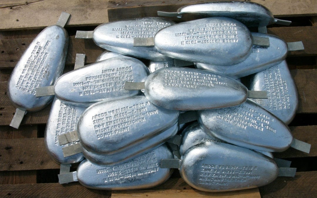
An external anode made from a more active metal (one that corrodes more readily than iron or steel) is connected to the metal surface to be protected. The anode’s own corrosion generates the CP current, making the protected metal the cathode.

2.    Impressed Current Systems

An external, direct current (DC) power source is connected to the steel, along with an inert anode in the electrolyte. The current flows from the anode,  onto the steel, turning it into a cathode.

Galvanic (Sacrificial) Anodes

Galvanic anodes are metal castings physically connected to the metal to be protected,. The anode material is chosen based on its more negative electrical potential compared to steel, as defined by their positions in the galvanic series.

The difference in potential between the sacrificial anode and the steel causes electrons to flow from the anode to the steel, making the steel surface more negatively charged and, thus, the cathode of the corrosion cell. The anode material corrodes or sacrifices itself to protect the steel.

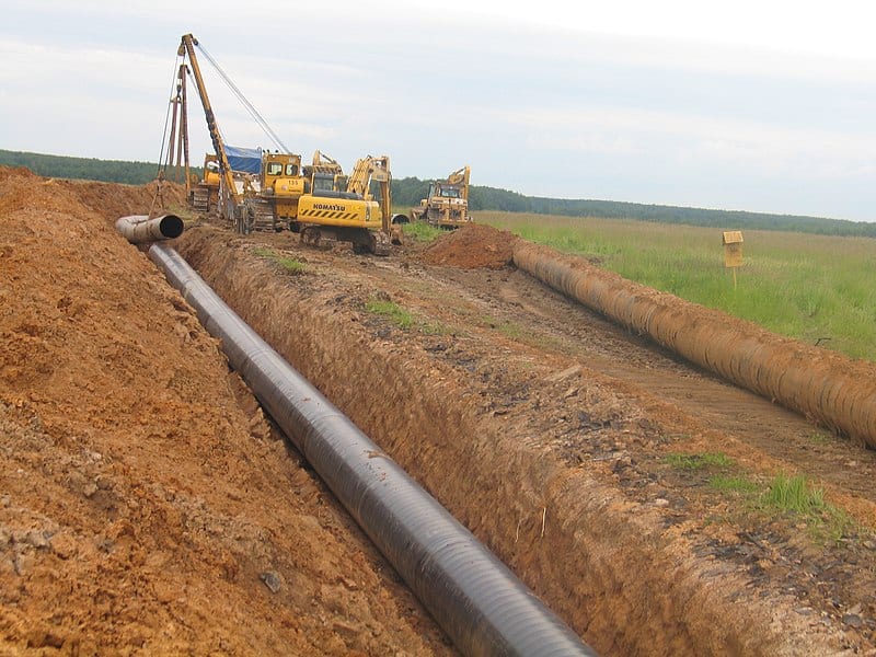
Common materials used for galvanic anodes include alloys of aluminum, zinc, and magnesium. These anodes are widely used in the protection of ballast and cargo/ballast tanks of ships, external hulls of smaller vessels, offshore oil and gas facilities, internal and external flood defense gates, and smaller buried tanks and pipelines.

In paint technology, zinc-rich primers act similarly to galvanic anodes. The zinc particles in the primer corrode preferentially to the steel substrate, providing protection. Galvanised steel also employs this principle, where the zinc coating corrodes to protect exposed steel areas if the coating is damaged.

Impressed Current Systems

For larger structures, the current demand might be too high for galvanic anodes alone, making them uneconomical. In such cases, impressed current systems are used, where an external DC power source is used to force electrons onto the steel surface.

Impressed current anodes are typically made from materials such as mixed metal oxide-coated titanium (MMO/Ti), platinum-coated titanium (Pt/Ti), niobium (Pt/Nb), or cast iron/silicon/chrome alloys (SiFe anodes).

In Summary

Both galvanic and impressed current CP systems operate on the principle of providing an excess of electrons to the metal surface, making it the cathode, and preventing corrosion. Key points to remember are:

  • CP can minimise corrosion damage to uncoated structures and to coated structures if the coating becomes damaged.
  • CP applied to external surfaces will not reduce corrosion on internal surfaces.
  • CP is ineffective above mid-tide level and does not affect atmospherically exposed steel.
  • The choice between galvanic and impressed current CP systems depends on the specific requirements and scale of the structure being protected.

In conjunction with industry experts, we have developed a comprehensive set of training and certification programs for all in the corrosion industry. These include our leading Cathodic Protection, Training, Assessment and Certification Scheme and Coating and Inspection Training. For details of these courses, please contact ICorr today.

In the last of this mini-series of articles covering cathodic protection and the corrosive reaction, we look at designing, monitoring, and integrating cathodic protection with coatings.

Designing, Monitoring, and Integrating Cathodic Protection with Coatings

Cathodic Protection: Understanding the Corrosive Reaction

Cathodic Protection: Understanding the Corrosive Reaction

Introduction to Cathodic Protection

For those working on painting tanks, pipelines, or ship hulls, it’s common to encounter cathodic protection (CP) specified alongside protective coatings to combat corrosion. Yet, for many paint technologists and applicators, CP remains a mystery.

This article serves as a foundational guide for understanding this technology, covering the basics of CP, and the nature of the corrosive reaction.

What is Cathodic Protection (CP)?

Cathodic protection (CP) is a method used to prevent metal corrosion by making the metal less corrosive in its environment.

This technique, first introduced by Humphry Davy in the 1800s, became more prominent in the early 1900s with patents for pipeline protection. The 1930s oil boom in North America highlighted its importance, as extensive corrosion led to frequent leaks in both coated and bare steel pipelines: CP, utilising zinc galvanic anodes and impressed current systems, proved effective in mitigating corrosion.

By 1938, CP was employed in marine terminal pipelines in Bahrain, and by the 1950s, it was a standard practice across Europe. Today, it is mandated for use in offshore oil and gas facilities, buried pipelines, and ship hulls requiring extended dry docking.

CP is effective for metals that are either buried, immersed, or encapsulated in a conductive medium such as steel in concrete or water-filled tanks. It is often used with protective coatings to prevent corrosion at points where the coating may be damaged, thereby extending the coating’s protective properties by preventing further corrosion, and undercutting.

The Corrosion Reaction

In the protective coatings industry, the primary concern is the protection of steel structures, so our focus will be on steel and iron.

Extracting a metal from its ore requires significant energy, which remains stored in the refined metal, making it unstable and prone to revert to its more stable state, such as iron reacting with oxygen in the air and turning into iron oxide – which we all call rust.

Corrosion is an electrochemical process – the combination of electricity with chemical processes.   When a corrosion occurs, an electric current (electrons) flows from the area that is corroding – known as the anode – to an area that is not corroding – known as the cathode.

CP works by forcing additional electrons into the anode areas which stops the corrosion reaction.  The extra electrons can be provided from an electrical power source or by attaching a more corrosive metal such as zinc or aluminium.

In Summary

Grasping the basics of cathodic protection and the principles of corrosion is essential if you are tasked with painting and protecting metal structures. Properly implemented CP can greatly extend the lifespan of coatings and metal structures, making it an invaluable tool in the battle against corrosion.

Our Fundamentals of Corrosion Course covers various aspects of corrosion, including:

  • Basic corrosion science
  • Common corrosion mechanisms; galvanic, crevice, pitting, deposition, corrosion under deposit/lagging, stress corrosion and cracking
  • Methods for preventing or managing corrosion, including Inhibitors/passivation
  • Introduction to cathodic protection
  • Surface preparation challenges, paints and coatings

It has been designed to be suitable for engineers, paint inspectors, designers, technicians, and scientists wishing to expand their career opportunities into the corrosion field or wanting to broaden or refresh their knowledge of corrosion in general.

To learn more about this course and the next course dates, contact our admin department today.

In our next article, we examine using cathodic protection to counteract the corrosive reaction.

Ask the Expert

Ask the Expert

Preventing Chloride Stress Corrosion Cracking (CSCC) and Degradation in Austenitic Stainless Steels

Dr Shagufta Khan, Ph.D., FICorr

  1. How can we prevent chloride stress corrosion cracking 
(CSCC) in austenitic stainless steels?

Chloride stress corrosion cracking (CSCC) is one of the most common reasons why austenitic stainless-steel pipework and vessels fail under service in the chemical processing and petrochemical industries however these lower stainless grades can be subject to a wide range of deterioration modes as detailed below.

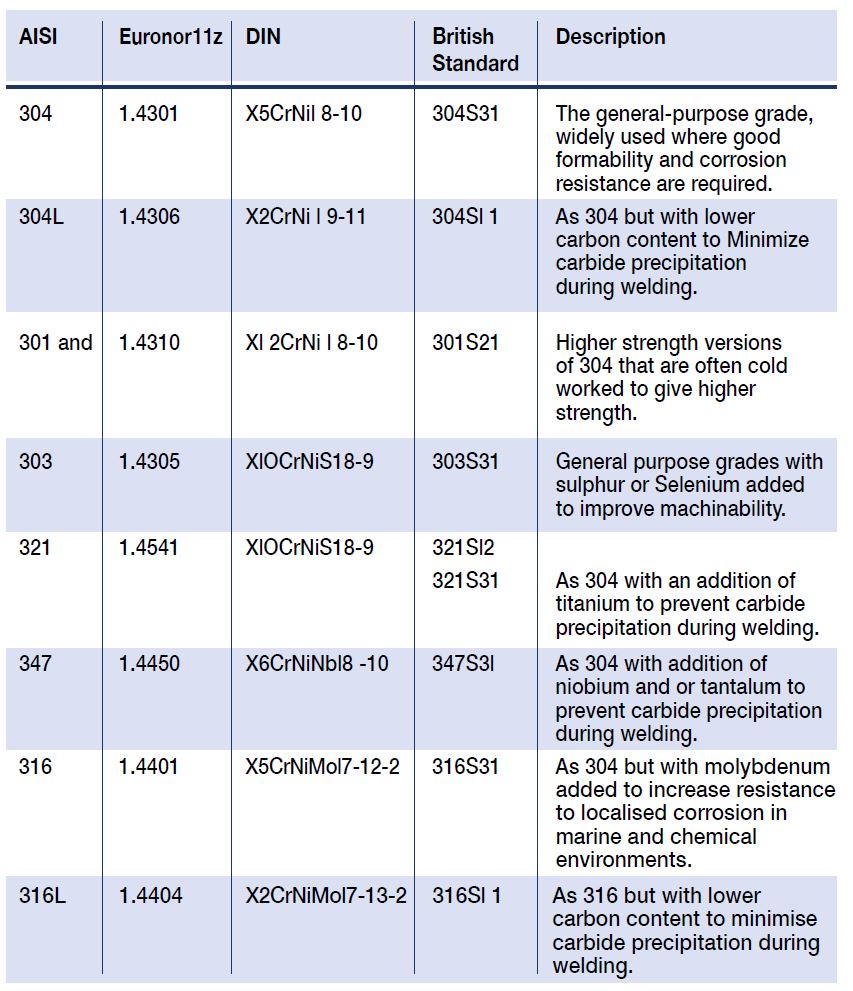
Stainless steels (SS) must contain a minimum of 11 Wt % chromium, and this level of chromium allows formation of a passive surface oxide that prevents surface corrosion in an unpolluted atmosphere. Increasing Cr content to 17 to 20 %, as typical of the austenitic SS, or to 26 to 29 % as possible in newer ferritic SS, greatly increases the stability of the passive film. Examples of common grade modifications for different applications are given below in Table 1.

AISI          Euronor11z                                 DIN               British
                Description
                                                       Standard

304           1.4301          X5CrNil 8-10         304S31        
The general-purpose grade, widely used where good formability and corrosion resistance are required.

304L         1.4306          X2CrNi l 9-11         304Sl 1        
As 304 but with lower 
carbon content to Minimize                   carbide precipitation                  during welding.

301 and                    1.4310                    Xl 2CrNi l 8-10      301S21       
Higher strength versions of 304 that are often cold worked to give higher strength.

303      1.4305          XlOCrNiS18-9       303S31        
General purpose grades with sulphur or Selenium added 
to improve machinability.

321           1.4541          XlOCrNiS18-9       321Sl2

321S31        
As 304 with an addition of titanium to prevent carbide precipitation during welding.

347           1.4450          X6CrNiNbl8 -10    347S3l         
As 304 with addition of niobium and or tantalum to prevent carbide precipitation during welding.

316           1.4401          X5CrNiMol7-12-2  316S31        


As 304 but with molybdenum 
added to increase resistance to localised corrosion in          marine and chemical                environments.

316L         1.4404          X2CrNiMol7-13-2 316Sl 1       
As 316 but with lower           carbon content to minimise carbide precipitation during welding.

Austenitic SS can have an excellent combination of mechanical strength, corrosion resistance, ease of fabrication, and cost effectiveness.  The most widely used stainless steel grades are austenitic, with 74% production of total world SS production. Various grades of austenitic steels have excellent corrosion resistance in many environments, resisting attack by the atmosphere and by many industrial gases and chemicals.

The pitting and crevice corrosion resistance of stainless steel is primarily determined by the content of chromium, molybdenum and nitrogen. Manufacturing and fabrication practices, e.g. welding, are also of vital importance for the actual performance in service. A parameter for comparing the resistance to pitting in chloride environments is the 
PRE number (Pitting Resistance Equivalent).

The PRE is defined as, in weight-%

PRE = %Cr + 3.3 x %Mo + 16 x %N

Many of these stainless steels have good strength at high temperatures which accounts for their wide use at elevated temperatures. They are also among the primary materials selected for use at extremely low temperatures, since they do not become brittle compared to other types of steel. AISI 304 and 304L are the most popular grade of austenitic SS. Although austenitic SS are used as corrosion resistance alloys for many applications, there are many cases of failure in aggressive environments. Some of the corrosion failure types that stainless steel remains susceptible to include:

  • 
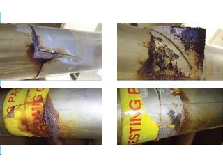
Crevice corrosion (common, often seen at piping flanges and under identification labels).
  • 
Galvanic/bimetallic corrosion (common, must have compatible fixings/fasteners).
  • 
Pitting corrosion (very common especially under labels, can occur in storage or at fabrication site prior to service).
  • 
Stress corrosion cracking (common at more elevated temperatures and where there are residual stresses).
  • 
Weld decay (less common, varies with process chemistry and applied chemical treatments).

SCC

Stress corrosion cracking is a time-dependent phenomenon that occurs in a metal when certain metallurgical, mechanical, and environmental, conditions are present at the same time. SCC is a somewhat sneaky type of degradation because it occurs at stress levels within the design stress range. The cracking can be:

  • Intergranular (IG): passing through the grain boundaries.
  • Trans granular (TG): passing through the grain matrix.
  • A mixed mode (TG and IG) of SCC,

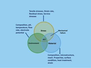
Depending on the microstructure of the material exposed to the atmosphere and the nature of the environment. SCC is caused by weak tensile stresses, typically below the macroscopic yield stress. Figure 3 describes the necessary conditions for SCC to occur. Austenitic stainless steels may undergo SCC in hot, concentrated chloride solutions, chloride-contaminated steam, and in HTHP (high temperature and     high pressure) demineralised water in presence of oxygen.

Among all types of environmentally assisted cracking of austenitic stainless steel, CSCC is perhaps the most common. Many 
incidences of failure have been reported due to CSCC, e.g. 
condenser tubes in heat exchangers, swimming pool components, 
parts used in marine applications, under insulation of external piping 
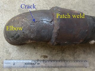
in a refinery, and medical devices. Chloride stress corrosion 
cracking of patch repaired elbow in hydrocarbon service is shown 
in Figure 4.

API 571 defines chloride stress corrosion cracking as follows: “Surface initiated cracking of 300 series SS and some nickel-based alloys under the combined action of tensile stress, temperature, and an aqueous chloride environment. It is also referred to as chloride cracking”.  All 300 series SS are highly susceptible to pitting and CSCC where additional stresses exist. Welds in 300 series SS normally contain some ferrite, producing a duplex structure that is usually more resistant to CSCC than the base 
metal though.

Factors Affecting CSCC: Several environmental factors, like chloride concentration, temperature, pH, dissolved oxygen can have profound effect on CSCC. Nickel content of alloy and applied or residual tensile stresses can also affect CSCC.

Chloride Concentration:  CSCC is caused by inorganic chloride ions. It is known that organic chlorides do not directly cause CSCC.  In industrial processes, hydrolysis or thermal decomposition of organic chlorides may produce ionic, inorganic chlorides. Therefore, organic chlorides can also cause CSCC. The components experiencing higher tensile stresses require lower Cl- concentration for initiation of SCC. There is no lower limit of Cl- concentration for crack initiation. A few ppm Cl- in the process stream can concentrate to hundreds of ppm where evaporation takes place. Cl- can further concentrate at the base of pits when pitting corrosion starts. Increasing levels of chloride will increase the likelihood of cracking and greater than 50g/L of chloride in process fluids would certainly give cause for concern for 300 series SS.

Temperature:  Increasing temperatures increase the cracking probability if tensile stress and an aqueous chloride solution and/or external chloride build-up are present.  Although exceptional cases have been reported. Highly cold worked or sensitised materials may undergo cracking at lower temperature or even at ambient temperature. Usually cracking occurs at metal temperatures above about 50 °C and this temperature limit is considered the guideline for fixed equipment in the refining industry.

Tensile Stresses:  Tensile stress may be applied or residual. Crack initiation and propagation are guided by the aggregate of both external (i.e. applied) and internal residual stresses. Residual stress by definition is the tensile, or compressive force, that exists in the bulk of a material without application of an external load. The bending of steel plates during pipe construction, localised plastic deformation during handling, and differential cooling through the wall thickness and along the surface during rolling, are all potential sources of residual stresses in pipeline steels. Regions with different microstructures and chemical segregation at the grain boundary may also generate residual stresses in metallic components. In the absence of proper control measures, residual stresses produced during the fabrication phase can significantly contribute to SCC. Non-stress-relieved welds, highly stressed, or cold worked components, such as expansion bellows, are highly susceptible to cracking.

pH of Environment:  Cracking is more likely to occur at lower pH. However, SCC usually does not occur at pH values below 2. Uniform corrosion generally predominates at such highly acidic range. CSCC tendency decreases toward the alkaline pH region.

Dissolved Oxygen:  It is observed that oxygen dissolved in the water increases tendency to SCC. Other oxidisers in addition to oxygen (e.g., CO and CO2) can also enhance CSCC. It is unclear what oxygen concentration must be reached before CSCC starts.

Nickel Content:  Alloys tendency to SCC is affected by nickel content in a profound way. Stainless steels with a nickel content of 8 % to 12 % have greatest susceptibility toward SCC. Alloys with nickel contents above 35 % are highly resistant, and alloys above 45 % show near immunity in refining applications, but severe conditions may lead to cracking in these alloys.

Prevention of CSCC:  Prevention of CSCC by applied coatings is common in the energy sector although can be more difficult to achieve with smaller diameter piping. Reduction of tensile stress can be used to avoid CSCC.  This can be achieved by applying compressive stress by shot peening. A suitable high-temperature stress relief heat treatment of 300 series SS after fabrication will reduce residual stresses. Care should be taken that stress relief heat treatment should not result in sensitisation.

Changing process conditions is the best approach for minimizing CSCC. The acidity and corrosiveness of the process fluids can be controlled by addition of chemicals such as acid neutralizer and corrosion inhibitors. Effectiveness of corrosion inhibitors must be assured before use through laboratory test. Upgrading the metallurgy may also be opted to avoid SCC. A duplex SS might be considered for this purpose. Duplex SS has almost equal ratio of austenitic and ferritic grains in its microstructure. Duplex SS have very good corrosion resistance and they can withstand higher tensile stresses. Their resistance to pitting corrosion is also very good. Super austenitic SS have higher content of Ni so they show good resistance to cracking in chloride environments.

Low chloride-content water should be used during hydrotesting, followed quickly by thorough dry out. Designs that create stagnant regions should be avoided as chlorides can concentrate in such region. An effective external coating (e.g. epoxy phenolic coatings up to 120 oC and TSA above this temperature limit) should be applied to SS piping and equipment prior to insulating or adding piping identification. Shrink-wrapped PVC labels, coatings, or label adhesives with high levels of chlorides or other halogen ions should be avoided.

References

  1. J. F. Grubb, T. DeBold, J. D. Fritz, Corrosion of Wrought Stainless Steels, in: S. D. Cramer, B. S. Covino (Eds), Corrosion: Materials, Vol 13B, ASM Handbook (tenth edition), ASM International, Ohio, 2005, p. 54-77.
  2. A. J. Sedriks, Corrosion of stainless steels, second ed., John Wiley and Sons, New York, NY, 1996.
  3. ANSI/API Recommended Practice 571 Third Edition, March 2020, Damage mechanisms affecting fixed equipment in the refining industry.
  4. M. Hussain, T Zhang, S Khan, N Hassan, Stress corrosion cracking is a threat to pipeline integrity management, Corrosion and prevention 2020, Perth Australia organised by Australian corrosion association.
  5. S. Khan, Doctoral thesis “Corrosion of austenitic stainless steels in nitric acid at trans passive potentials: effect of material and process parameters, 2016, Homi Bhabha National Institute, India.
  6. Chidambaram Subramanian, chloride induced stress corrosion cracking of repaired pipe elbow from an oil refinery: forensic analysis.

CAPTIONS:

Table 1: Widely Used Grades of Austenitic Stainless Steel

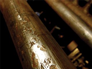
Above: Figure 1: Commonly Observed 316L Grade Stainless Pitting Under Labels.

Left: Figure 2: Photo of Corrosion Under Labels (CUL) Seen After Label Removal.

Figure 3: The Necessary Conditions for SCC to Occur in Austenitic Stainless Steel.


Figure 4: Photo of Patch Repaired Piping Elbow from Hydro Cracking Plant (Corrosion Management, Issue 174).