


High-Temperature Degradation in Chlorine and Sulphur-Rich Environments: Mechanisms and Mitigation Using ArcSprayed Coatings

High-Temperature Degradation in Chlorine and Sulphur-Rich Environments: Mechanisms and Mitigation Using ArcSprayed Coatings

Ahmad Usman, Group Innovation R&D Engineer, Welding Alloys Group UK

Meet The Author

Ahmad Usman is a Group Innovation R&D Engineer at Welding Alloys Group UK, specialising in high-temperature material degradation in demanding industrial environments. He works with a multidisciplinary team to design alloys that resist corrosion and wear in heavy industry applications. His expertise in thermal spray coatings enables him to address complex challenges through practical, performance-driven solutions. His work focuses on real-world case studies to develop materials that protect critical components and extend service life under extreme conditions.

Ahmad is part of a global research and innovation team committed to technical excellence and supporting industrial partners in advancing their products and services. His research interests focus on the future performance of materials in increasingly aggressive operating environments.

Introduction

Material degradation at high temperature remains a critical challenge across a wide range of industrial sectors, including chemical processing, aerospace, gas turbines, energy generation, refining and petrochemical processing, and metallurgical operations (Spiegel, Zahs, and Grabke 2003). Components operating under such conditions are exposed to reactive gaseous and condensed species, leading to reduced operational efficiency, increased maintenance demands, and ultimately premature component failure. These challenges carry significant economic

and operational consequences, underscoring the importance of understanding and mitigating high-temperature degradation processes (Khantisopon et al. 2022).

The nature and severity of degradation are strongly influenced by the local chemical environment, which is governed by factors such as process conditions, feedstock composition, and deposit chemistry (Corrosion Basics Understanding the Basic Principles and Causes of Corrosion

n.d.). In oxygen-rich environments, protective oxide scales may form and provide a degree of resistance; however, under oxygen-deficient conditions, the stability of such layers is compromised, increasing susceptibility to accelerated attack. The presence of sulphur- and chlorine-containing species further complicates these processes by introducing additional degradation pathways (Floreen and Kane n.d.). Sulphur-rich environments typically promote sulphide formation, while chlorine-containing species can induce active oxidation through the formation and volatilisation of metal chlorides, resulting in rapid material loss (Sadeghimeresht et al. 2018; Usman et al. 2025).

In practical systems, these mechanisms rarely occur in isolation. Instead, they evolve dynamically in response to local variatio in temperature, gas composition, and deposit accumulation, as shown in Figure 1 (Usman et al. 20 As a result, degradation behaviour is often highly heterogeneous, even within a single system, making material selection and lifetime prediction particularly challenging.
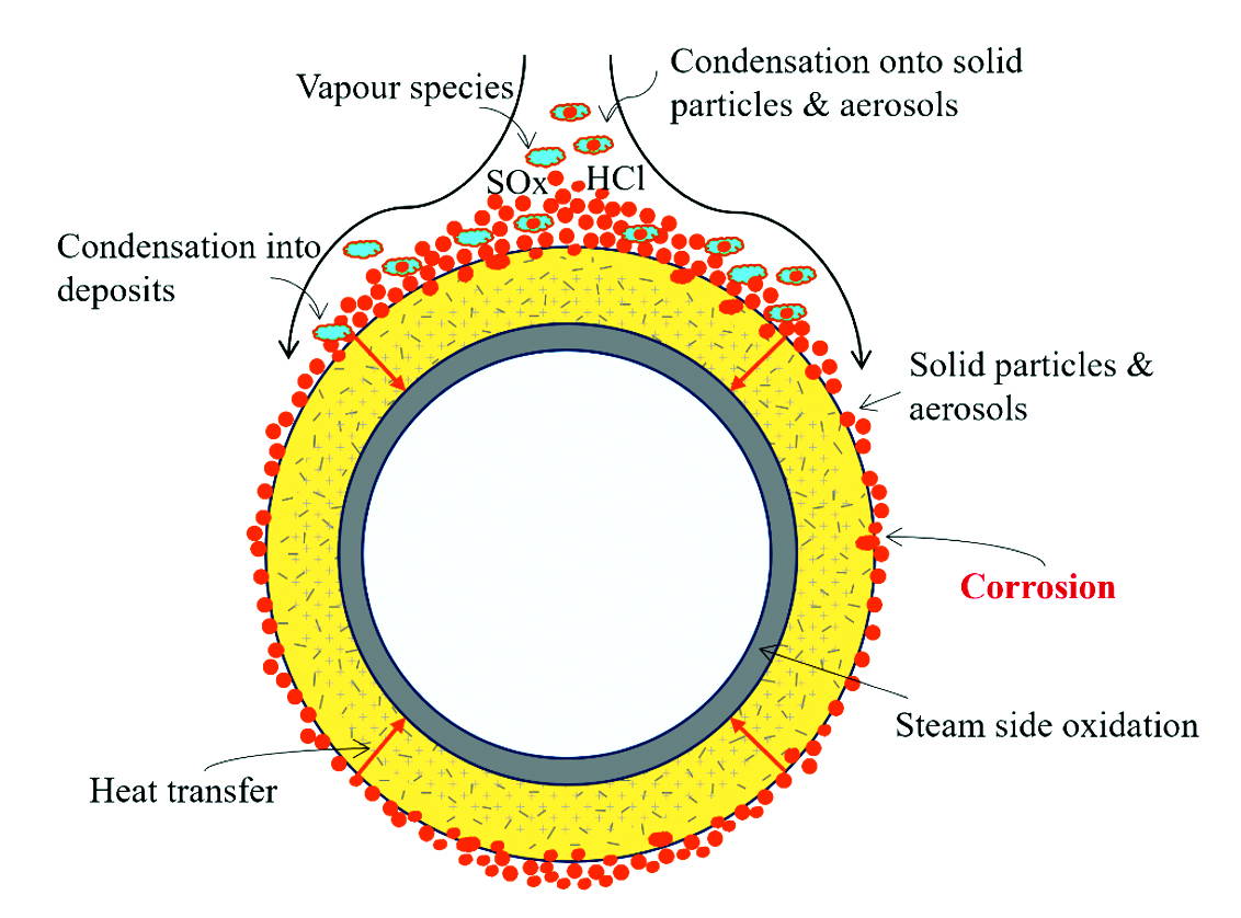
Figure 1: Schematic Representation of Corrosion Attack on a Metal Surface.

Although considerable research has been conducted in this field, many studies are based on simplified or controlled environments that do not fully capture the complexity of real operating conditions. Industrial systems exhibit significant spatial and temporal variability, leading to differences in dominant corrosion mechanisms across components.  Addressing this gap requires studies that integrate realworld observations with controlled experimental validation.

The present study adopts this approach by examining three industrial case studies representing distinct chemical environments. The objective is to identify the dominant degradation mechanisms under different conditions and to establish a mechanistic understanding based on post-exposure characterisation of materials and deposits. Alongside this analysis, the study evaluates the performance of thermally sprayed coatings as a mitigation strategy. These coatings offer a flexible and cost-efficient solution for protecting large components, particularly where in situ application is required (Usman et al. 2025). Among the available techniques, arc-sprayed coatings provide a practical balance between performance and deployability. This work therefore investigates the relationship between environmental conditions, degradation behaviour, and coating performance, with the aim of informing the design and selection of protective systems for high-temperature applications.

Industrial Case Studies

Three industrial case studies were selected to examine material degradation under distinct high temperature operating environments. Each case represents a different chemical regime, characterised by variations in deposit composition and gas-phase species, resulting in differences in dominant degradation mechanisms. Material samples were obtained from components exposed to high temperature service conditions. Post-exposure characterisation was carried out to assess both substrate degradation and deposit chemistry. Elemental analysis using scanning electron microscopy coupled with energy-dispersive X-ray spectroscopy (SEM-EDX) enabled identification of key reactive species and their distribution within the deposits and affected material regions.

Case Study 1: Chlorine-Dominated Environment

This environment is characterised by solid-fuel combustion conditions operating at relatively low temperatures (500-600 °C), which favour the condensation and accumulation of highly corrosive molten salt deposits on exposed component surfaces, as shown in Figure 2. Under these conditions, deposited species remain stable in the condensed phase, enabling sustained interaction with the underlying material.
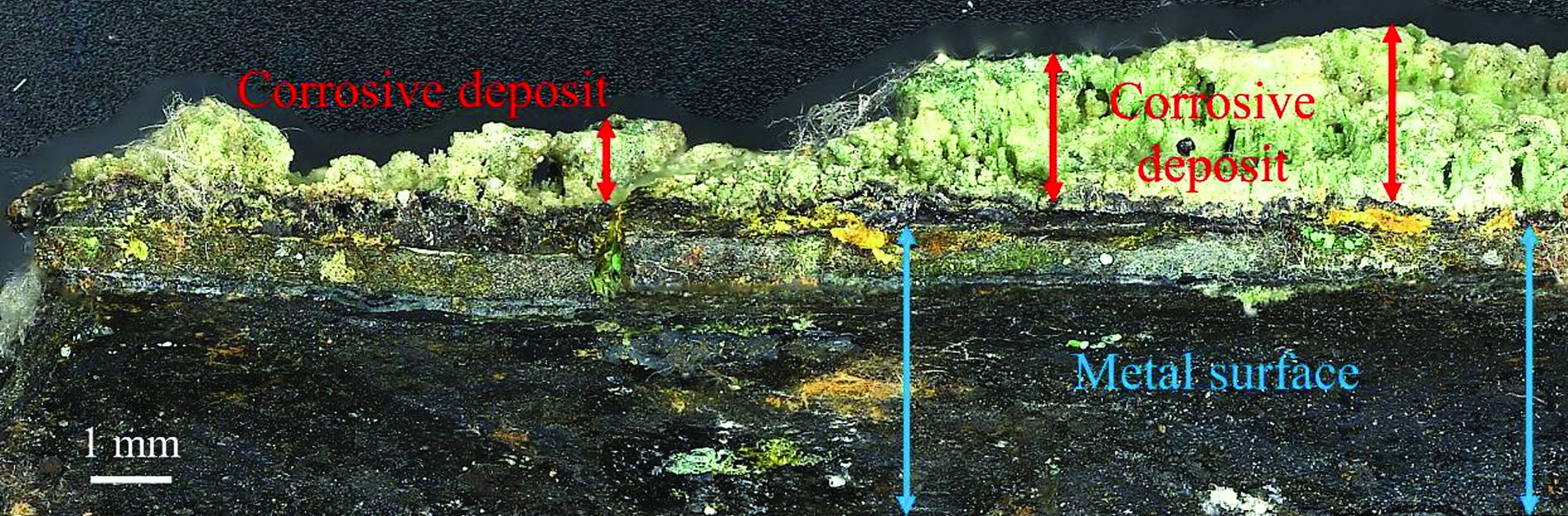
Figure 2: Deposit and Accumulation of Corrosive Deposits on the Exposed Component Surface.

Elemental analysis of surface deposits, as shown in Figure 3, revealed elevated concentrations of chlorine in combination with alkali metals (K, Na), along with iron and oxygen. The presence of alkali chlorides indicates a chemical environment conducive to active oxidation. In this mechanism, chlorine participates in cyclic reactions involving the formation of volatile metal chlorides at the metal-deposit interface. These metal chlorides subsequently migrate outward and re-oxidise in regions of higher oxygen partial pressure, regenerating chlorine species and sustaining the degradation process. This cyclic mechanism disrupts the formation of stable protective oxide layers, leading to accelerated material loss.
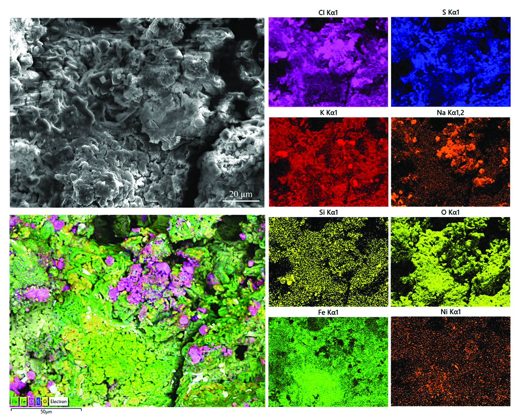
Figure 3: SEM-EDX Elemental Analysis of Surface Deposit from the Exposed Material Showing High Concentrations of Chlorine and Alkali Metals (K, Na).

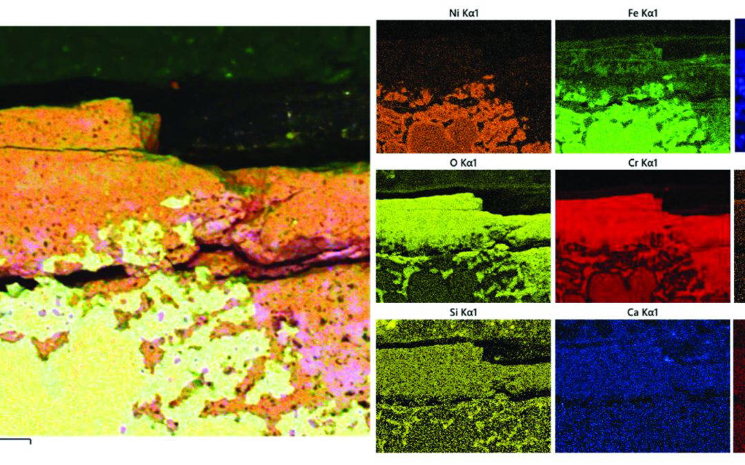
Microstructural observations from the degraded surface (Figure 4) show a porous morphology associated with outward-growing corrosion products. This porous structure is indicative of volatilisation-driven material transport, in which the formation and outward diffusion of metal chlorides result in a non-protective and mechanically weak scale. Elemental distribution maps obtained via EDX analysis (Figure 5) further confirm the localisation of chlorine within these regions, supporting the proposed mechanism of chlorine-driven degradation.
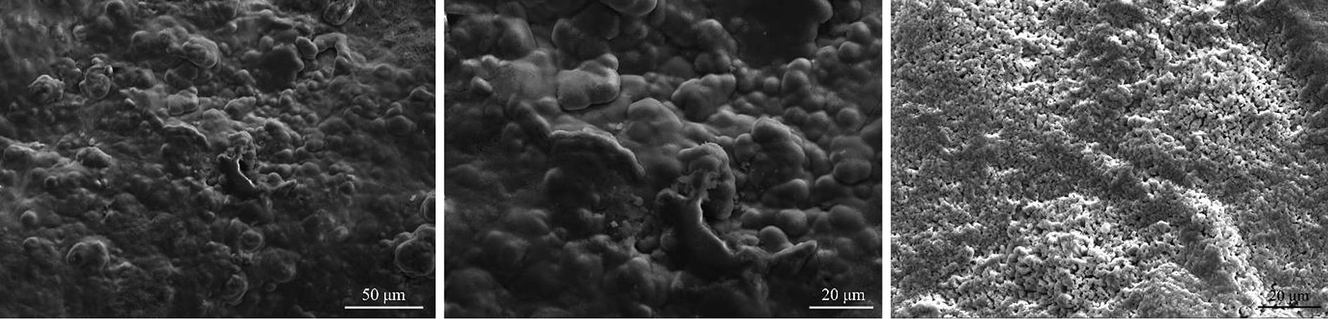
Above: Figure 4: Surface Morphology of Degraded Material Showing a Porous and Outward-Growing Corrosion Product Layer.
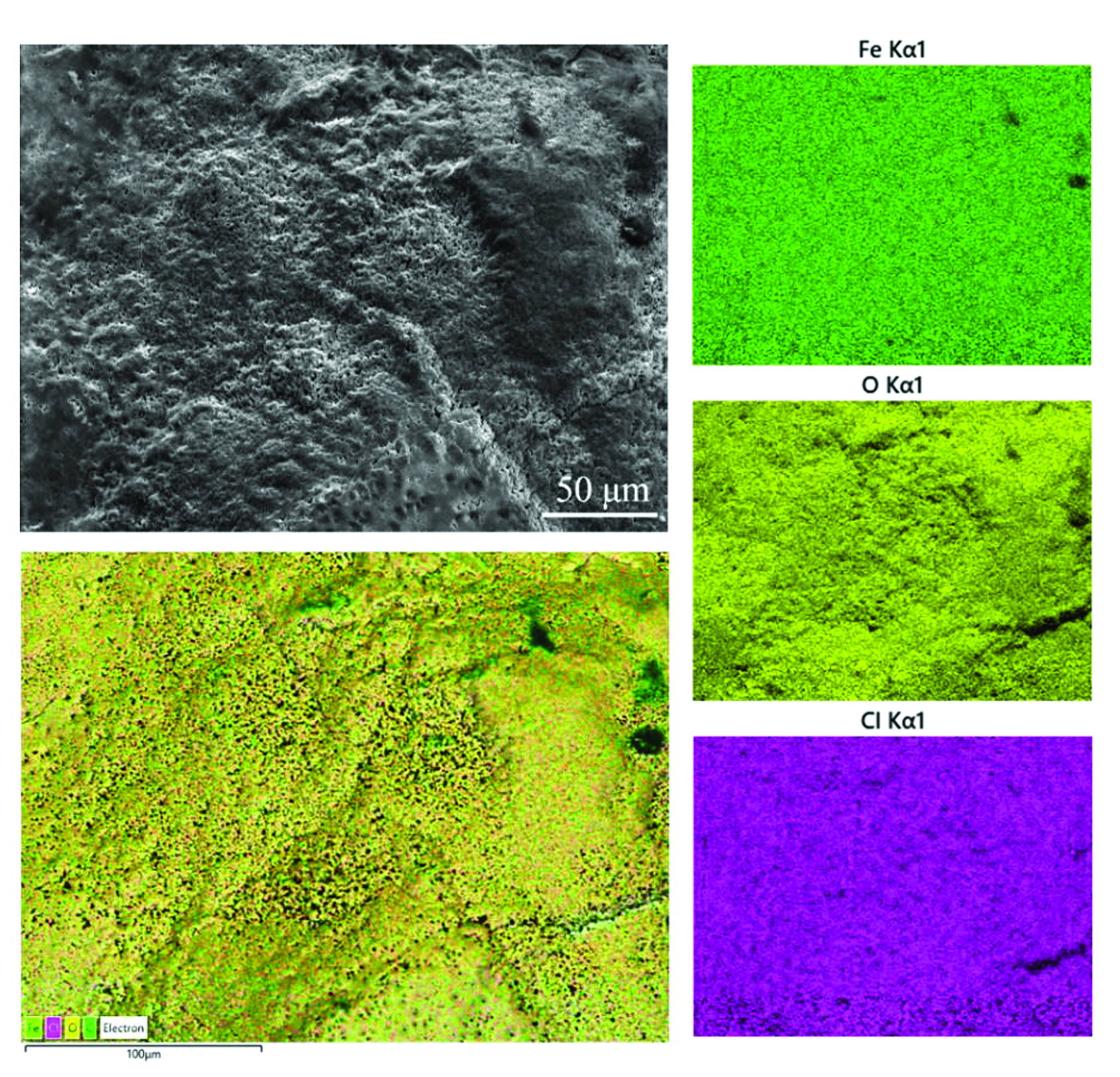
Figure 5: SEM-BSE and EDX Maps of Degraded Region Highlighting the Localisation of Chlorine within the Corrosion Products.

Case Study 2: Sulphur-Dominated Environment

In this study, a 310H stainless-steel component operated at approximately 800 °C under a low oxygen atmosphere with high moisture content. The environment contained sulphur-bearing species, including hydrogen sulphide, carbon disulphide, sulphur dioxide, and sulphur trioxide, along with other process-related compounds. Post-exposure analysis revealed significant sulphur enrichment within the degraded regions, accompanied by redistribution of alloying elements such as chromium, iron and nickel.

Microstructural examination (Figure 6) shows the formation of a layered surface scale, with evidence of cracking and localised breakdown. The outer region is enriched in chromium and oxygen, including the formation of a chromium-rich oxide layer; however, this layer appears discontinuous and mechanically unstable, exhibiting fracture and partial spallation.

Elemental distribution maps (Figure 7) further demonstrate that while chromium and oxygen are predominantly concentrated within the outer oxide layer, sulphur has penetrated beneath this layer into the underlying material.

Within these sulphur-enriched regions, iron and nickel remain present, suggesting the formation of sulphide phases within the substrate. This indicates that the protective oxide layer has been compromised, allowing inward diffusion of sulphur species.
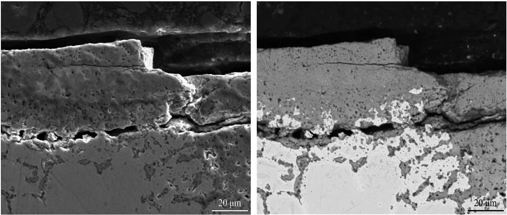
Figure 6: Cross-Sectional SEM Micrograph Showing the Layered Oxide Scale Formed on the Exposed Material.
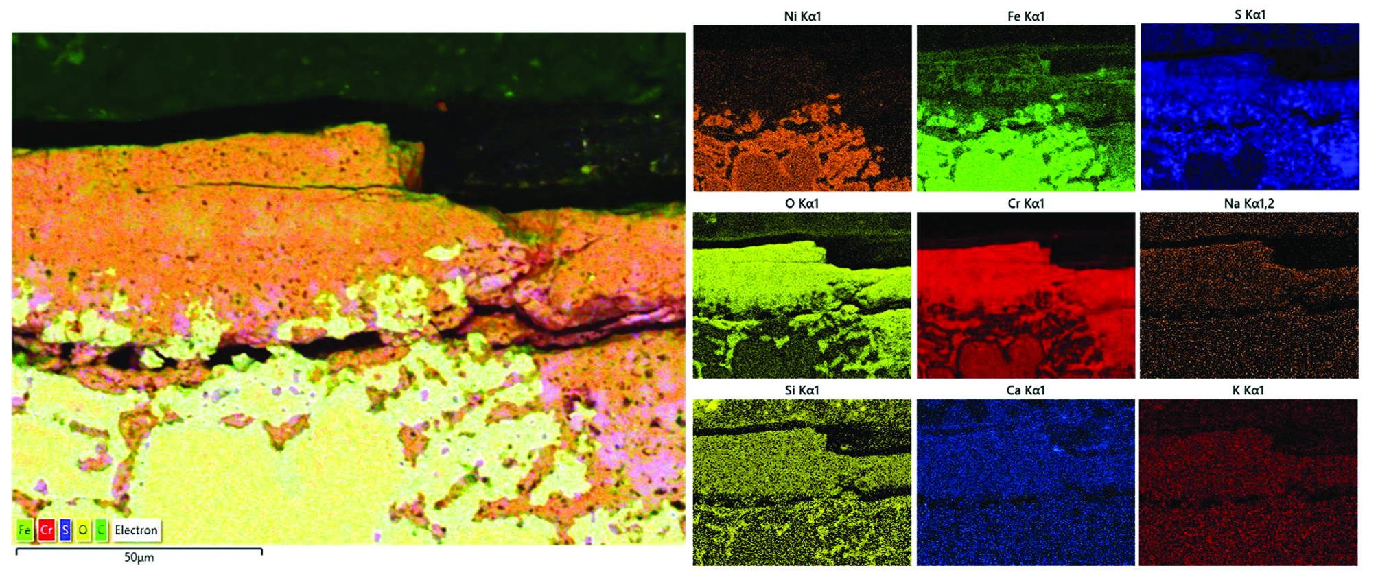
Figure 7: SEM-EDX Maps Illustrating Chromium and Oxygen Enrichment within the Outer Oxide Scale, Alongside Sulphur Penetration into the Underlying Material. The Co-Location of Iron and Nickel within Sulphur-Rich Regions Suggests Internal Sulphide.

 Case study 3: Mixed Chemical Environment

This case study exhibited the simultaneous presence of both sulphur and chlorine-containing species, along with alkali metals, indicating a mixed degradation regime.

Such environments are associated with competing and interacting mechanisms, including sulphide formation and chlorine-induced active oxidation, resulting in complex and often accelerated material degradation behaviour.

Elemental maps (Figure 8) from the degraded metal surface indicate the co-presence of chlorine and potassium within the same regions, suggesting the formation of KCl within the deposited salts. In contrast, sulphur is more widely distributed and associated with iron and oxygen.
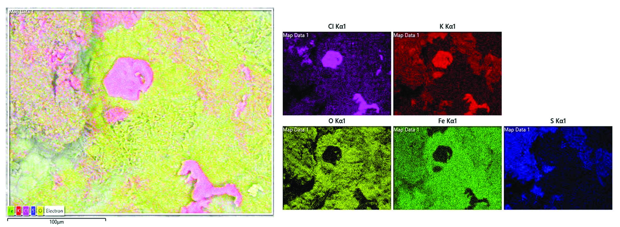
Figure 8: SEM-EDX Maps of the Degraded Surface Showing Co-Localisation of Cl and K, Indicating the Presence of KCl within the Deposits. Sulphur is More Broadly Distributed and Associated with Fe-Rich Regions.

 Cross-sectional SEM micrograph (Figure 9) reveals breakdown of the outer oxide scale, accompanied by intergranular attack within the underlying material. The oxide layer appears discontinuous and locally disrupted, reducing its protective capability. Further insight from elemental maps (Figure 10) shows that sulphur, chromium, and potassium are concentrated along the grain boundaries, indicating preferential penetration along these paths. This behaviour suggests that grain boundaries act as fast diffusion pathways, facilitating the ingress of aggressive species and accelerating localised degradation within the material.
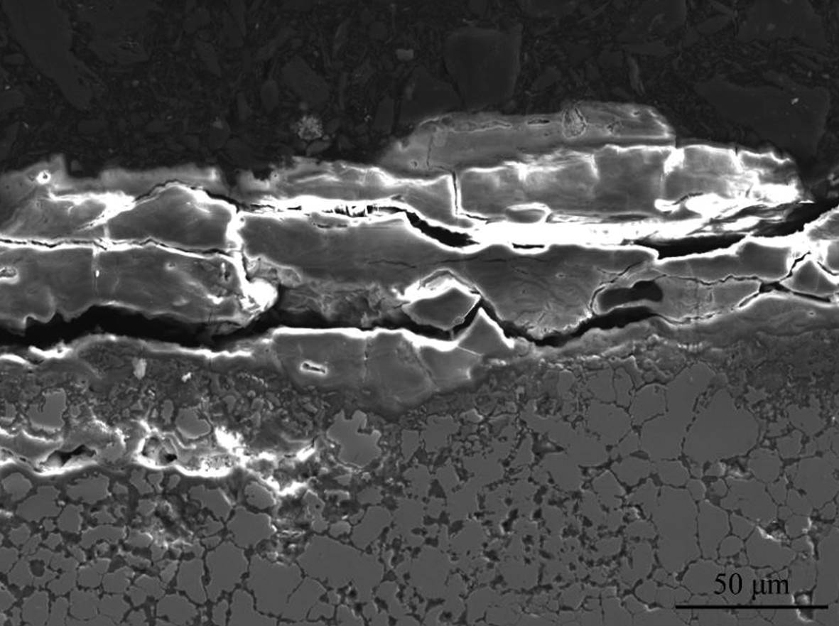
Figure 9: Cross-Sectional SEM Micrograph Showing the Presence of Intergranular Attack within the Underlaying Material.
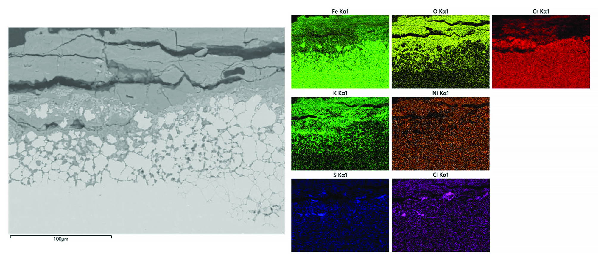
Figure 10: Elemental Distribution Maps Showing the Concentration of Sulphur, Chlorine, and Potassium Along Grain Boundaries, Indicating Preferential Ingress of Reactive Species and Localised Degradation Along These Pathways.

Experimental Procedure and Material

Given the complexity of the three operating conditions identified in the above case studies across different environments, controlled laboratory-scale high-temperature corrosion tests were designed and conducted. This approach was developed to systematically investigate the influence of key variables such as, temperature, exposure time, gas phase composition, and deposit chemistry on the corrosion process.

Arc-Spray Coating

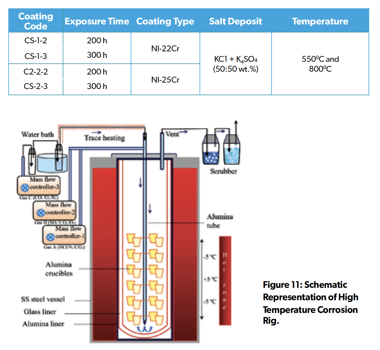
Two cored wire feedstocks were used to deposit coatings via the twin wire arc spraying (TWAS) process (details are reported in a previous study) (Usman et al. 2025). The Ni-based coatings, designated CS-1 and CS-2 (details provided in Table 1), were applied onto 310 H stainless-steel substrate. The coatings were deposited to a thickness of approximately 700 μm.

High-Temperature Corrosion Testing

Corrosion tests were conducted under highly aggressive simulated environments containing CO2, SO2, H2O, O2, HCl, and N2 at temperatures of 550 and 800 ± 5 °C, with exposure durations of 200 h and 300 h. A vertically oriented alumina-lined tube furnace (Figure 11) was used to carry out the high temperature corrosion tests under a controlled atmosphere (Waeytens et al. 2023). Coating samples were evaluated under deposited salt conditions comprising KCl and K2SO4. Before testing, coupon samples and crucibles were ultrasonically cleaned in acetone, followed by drying on a hot plate at 100 °C for 1 h before initial weighing. The combined mass of the crucibles, samples, and deposited salts was recorded to determine the applied deposit quantity.

Table 1: Samples Identification Codes and Experimental Conditions.
Post-Exposure Analysis

Following 200 h and 300 h of exposure, coating samples were assessed through cross-sectional microstructural analysis. Samples were sectioned, cold-mounted in low-shrinkage epoxy resin, and prepared using standard metallographic procedures, followed by polishing to a 1 μm diamond finish using an oil-based system. The cross-sectional microstructures were examined using digital microscopy to evaluate coating integrity, thickness variation, and degradation features.

Dimensional Metrology

Coating performance was further quantified using dimensional metrology to assess material loss and degradation (Waeytens et al. 2023). Thickness measurements were obtained along the perimeter of the exposed coatings. Multiple measurements were collected to ensure statistical relevance, and the data were compared with pre-exposure thickness values. These measurements were used to develop probability models describing coating degradation and to estimate coating lifetime under the tested conditions.

Results and Discussion

Microscopy Image Analysis Cross-sectional optical microscopy was performed on all eight coatings following high-temperature corrosion exposure. The micrographs presented in Figure 12 and Figure 13 indicate that all coatings experienced varying degrees of surface degradation. However, the CS-2 coatings exhibited comparatively lower damage than the CS-1 coatings at both temperatures. At 550 °C (200 h and 300 h), the CS-1 coatings showed pronounced localised attack, leading to the formation of a porous and non-adherent oxide scale. At 800 °C, the degradation was significantly more severe, as evidenced by the development of a highly porous surface morphology and coating delamination after 300 h of exposure. In contrast, the CS-2 coatings formed a relatively uniform and more adherent oxide layer at 550 °C, with only limited pitting observed at isolated locations. At 800 °C, although the severity of attack increased, the coatings continued to exhibit protective behaviour, with no significant spallation or deep interfacial corrosion observed. 
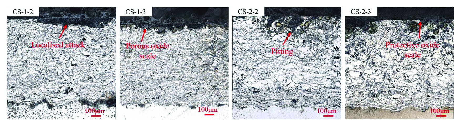
Figure 12: Cross-Sectional Optical Microscopy Images of Samples After Exposure at 550 °C for 200 h (CS-1-2, CS-2-2) and 300 h (CS-1-3, CS-2-3).
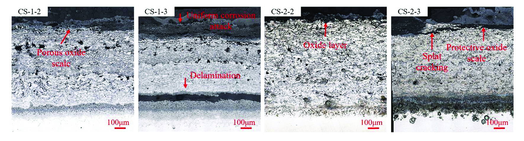
Figure 13: Cross-Sectional Optical Microscopy Images of Samples After Exposure at 800 °C for 200 h (CS-1-2, CS-2-2) and 300 h (CS-1-3, CS-2-3).

Dimensional Metrology

Dimensional metrology analysis was used to evaluate the corrosion performance of coating systems by generating statistical distributions of material loss. The median coating loss values (Figure 14) represent the extent of degradation in the exposed specimens. Figure 14 summarises the corrosion performance of coatings CS-1 and CS-2 exposed to simulated environments at 550 and 800 °C. Across all conditions, CS-2 consistently exhibited lower material loss compared to CS-1, indicating superior resistance to high-temperature degradation. For CS-2-2, the median coating loss was approximately 0.4 mm after 200 h at 550 °C, increasing to 1.0 mm after 300 h. At 800 °C, the corresponding values increased to 0.8 mm and 1.5 mm after 200 h and 300 h, respectively. In contrast, CS-1-2 showed significantly higher degradation, with median coating loss values reaching 5.0 mm after 200 h and 7.9 mm after 300 h at 800 °C.
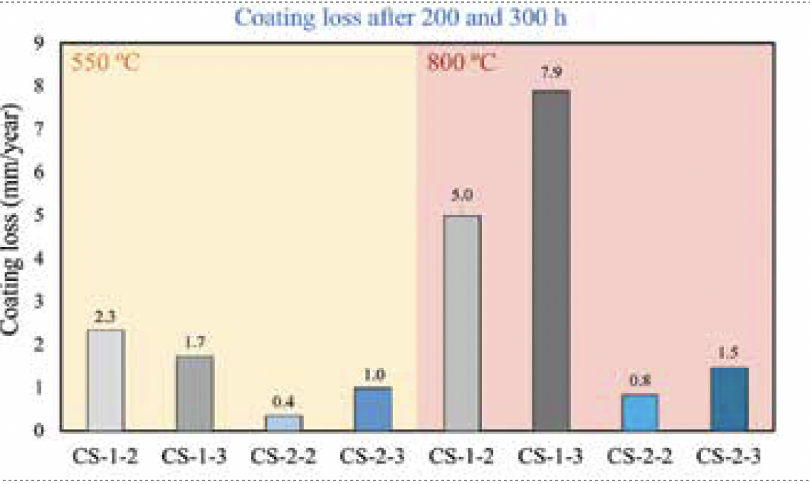
Figure 14: Median Coating Loss of KCl + K2SO4 Deposited Coating Samples Exposed to Aggressive Environments at 550 °C and 800 °C for 200 h and 300 h.

Conclusion

This study investigated high-temperature degradation mechanisms across three industrial environments characterised by chlorine-dominated, sulphur-dominated, and mixed chemical conditions and evaluated the performance of twin-wire arc-sprayed Ni-based coatings under simulated laboratory conditions.

• Chlorine-rich conditions led to the formation of porous, non-protective oxide scales, while sulphur rich environments promoted sulphide formation and internal degradation. Mixed environments resulted in complex attack, including oxide breakdown and intergranular corrosion.

• TWAS coating performance varied significantly between the two systems, with CS-2 consistently outperforming CS-1 under all test conditions. Lifetime modelling confirmed lower material loss for CS-2, demonstrating its superior protective performance at both 550 °C and 800 °C.

• The results highlight the importance of coating composition and microstructure in controlling oxide stability and limiting the ingress of corrosive species. Crucially, a detailed understanding of the underlying degradation mechanisms provides a foundation for the rational design of improved coating materials with enhanced performance in aggressive environments.

Acknowledgements

Special thanks are extended to Dr Adnan Syed, Dr Luis Isern and
Prof John Nicholls from the Centre for Materials at Cranfield University for their technical support in interpreting case study data and corrosion mechanisms, as well as in the development of methodologies enabling coating trials under aggressive conditions. The author also acknowledges Dr Mario Cordero from Welding Alloys Group for his support in the design of new alloy chemistries, which demonstrated good resistance under laboratory conditions, and for his support with arc spray
coating deposition.

References

1. M Spiegel et al, “Fundamental aspects of chlorine induced corrosion in power plants,” Materials at High Temperatures, 2003, 20(2), pp. 153–159. https://doi.org/10.1179/mht.2003.018

2. K Khantisopon et al, “High-temperature corrosion investigations of deposit containing eutectic KCl-K2SO4 mixture on AISI 1015 and SS304 steels,” Corrosion Science, 2022, 205, pp. 110470. https://doi.org/10.1016/j.corsci.2022.110470

3. C orrosion Basics: Understanding the Basic Principles and Causes of Corrosion, Materials Performance, 2011, 50, pp.88.

4. S Floreen and R H Kane, “The sulfidation attack of a nickel-base alloy at intermediate temperatures,” Metallurgical Transactions, 1984, 15A, pp. 5-10.

5. E Sadeghimeresht et al, “Chlorine-induced high temperature corrosion of HVAF-sprayed Ni-based alumina and chromia forming coatings,” Corrosion Science, 2018, 132, pp. 170–184.
https://doi.org/10.1016/j.corsci.2017.12.033

6. A Usman et al, “Fireside corrosion behavior of thermally sprayed coatings for waste-to-energy power plant applications,” Journal of Materials Engineering and Performance, 2025, 34(19), pp. 22393–22405. https://doi.org/10.1007/s11665-025-11630-7

7. M Waeytens et al, “A microscopy study of nickel-based superalloys performance in Type I hot corrosion conditions,” Materials at High Temperatures, 2023, 40(4), pp. 272–282. https://doi.org/10.1080/09603409.2023.2188355

Reducing Detection Time for Sulphate-  Reducing Bacteria in Industrial Water Systems  Les Merrill, CEO, Retego Labs

Reducing Detection Time for Sulphate- Reducing Bacteria in Industrial Water Systems Les Merrill, CEO, Retego Labs

Reducing Detection Time for Sulphate- Reducing Bacteria in Industrial Water Systems
Les Merrill, CEO, Retego Labs

Bacterial contamination does not always lead to material degradation, however, microbiologically influenced corrosion (MIC) continues to present a significant operational and economic challenge across a wide range of industrial sectors, including oil and gas systems, water treatment, and process industries.
A substantial proportion of corrosion-related failures are associated with MIC [1], a complex process in which microbial activity alters localised chemical conditions at metal surfaces, accelerating degradation.

Among the microbial groups implicated in MIC, sulphate-reducing bacteria (SRB) are widely regarded as one of the most significant contributors [2]. These anaerobic microorganisms reduce sulphate to hydrogen sulphide (H2S), a corrosive species that can promote pitting, contribute to sulphide stress cracking, and interfere with corrosion inhibition strategies. The presence of SRB is also associated with oilfield reservoir souring and operational inefficiencies in industrial systems. Despite the well-established role of SRB in corrosion processes, effective monitoring of these organisms remains challenging. Traditional detection methods often involve extended incubation periods or sophisticated laboratory-based analysis, limiting the ability of operators to respond rapidly to changing microbial conditions. As industrial systems increasingly move toward predictive and proactive maintenance strategies, there is a growing need for faster, field-applicable methods of detecting microbial activity.

Limitations of Conventional Detection Techniques

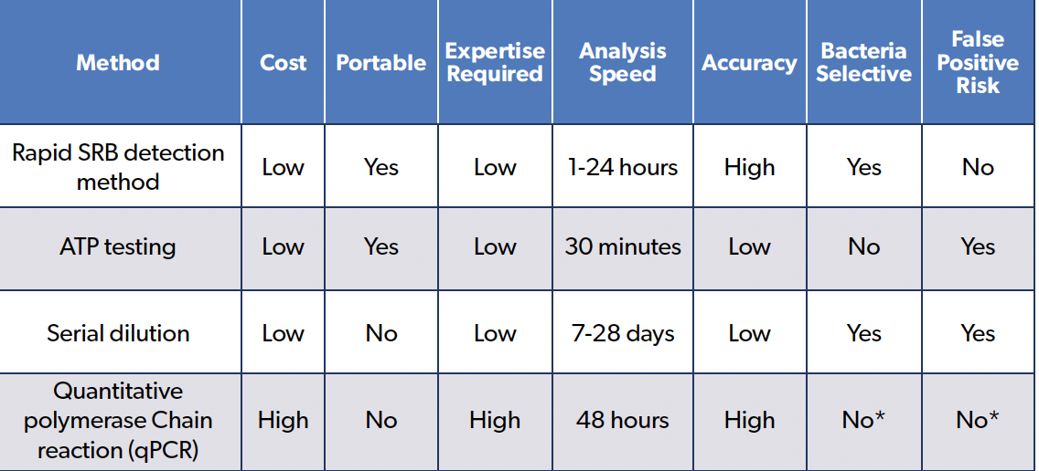
Table 1. Comparison of Conventional and Rapid SRB Detection Methods.

*Note: qPCR selectivity depends on the DNA target primers; however, it cannot distinguish between viable and non-viable microorganisms without propidium monoazide (PMA) sample optimization.

A range of analytical methods has been developed to detect and quantify sulphate-reducing bacteria in industrial water systems. These include culture-based techniques, serial dilution methods, and molecular approaches such as qPCR.

Another commonly used approach utilises adenosine triphosphate (ATP) testing, which measures total microbial activity by quantifying cellular energy present in a sample. While ATP testing provides rapid results and is useful for assessing overall biological activity, it does not distinguish between specific microbial groups such as SRB, limiting its ability to directly assess SRB-related corrosion risk. ATP testing is additionally susceptible to false positives, as it can have difficulty distinguishing between viable and non-viable bacteria [4].

Culture-Based and Serial Dilution Methods

Culture-based methods, including the serial dilution most probable number (MPN) technique, remain widely used due to their relative simplicity, ease of on-site use and historical acceptance [3]. These approaches rely on the growth of microorganisms under controlled conditions to estimate bacterial populations.

However, a key limitation of these methods is the time required to obtain results. Incubation periods may extend up to 28 days before observable changes occur, particularly in samples with low bacterial concentrations. During this time, environmental changes such as oxygen exposure, temperature variation
and sample handling can influence microbial activity and affect accuracy.

In addition, culture-based methods may underestimate microbial populations due to the inability to cultivate all organisms present in a sample, leading to incomplete assessment of microbial activity.

Molecular Techniques

Molecular approaches, including qPCR, offer faster detection compared to culture-based methods and can provide highly sensitive identification of microbial DNA, often within hours to days depending on sample logistics.

Despite these advantages, molecular methods require specialised laboratory infrastructure and trained personnel. Additionally, DNA-based detection does not necessarily indicate active metabolism, as genetic material from non-viable organisms may still be present [5], unless both propidium monoazide (PMA) and photoactivation protocols are optimized for each sample. This limitation can complicate interpretation when assessing current corrosion risk through overestimation of bacterial content.

Operational Implications

The extended timelines and logistical requirements associated with traditional detection methods can delay decision-making in corrosion management. In dynamic industrial environments, a delay of several weeks between sampling and results may result in missed opportunities for early intervention.

Emerging Approaches to Rapid Detection

Alternatives to traditional microbiological detection protocols have led to the development of methods that focus on measuring microbial activity rather than microbial growth. These approaches aim to provide faster and more relevant insights into the presence of metabolically active organisms.

A new method uses two key indicators of SRB activity:

• Enzymatic activity associated with microbial metabolism

• Production of hydrogen sulfide (H2S)

By targeting these indicators, it is possible to detect active SRB populations without prolonged incubation.

Case Example: Rapid Detection of SRB Activity

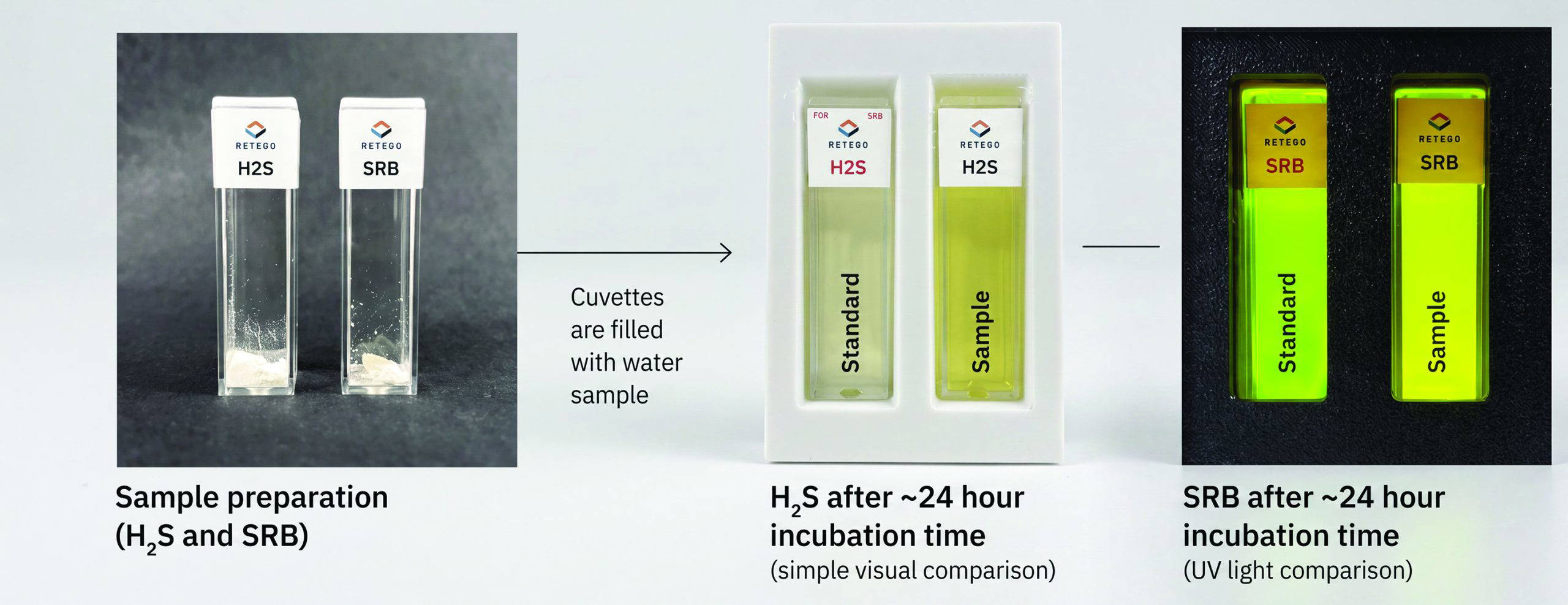
A field-deployable detection approach has been recently developed and evaluated that combines biological and chemical indicators to assess the presence of sulphate-reducing bacteria in water samples. The method employs two complementary detection pathways:

• Biological detection: Enzymatic activity from SRB produces a fluorescent signal through reaction with a substrate.

• Chemical detection: Hydrogen sulfide (H2S) from the sample reacts with a reagent to generate a visible color change.

These combined mechanisms allow for detection of active SRB without requiring propagation of the organism.

Rapid SRB Detection Workflow

Figure 1. Workflow for rapid detection of sulphate-reducing bacteria (SRB) and associated hydrogen sulfide (H2S) in water samples. Following sample preparation, results are obtained between 1 and 24 hours, with visual indicators distinguishing microbial activity through colorimetric and fluorescent responses. This workflow illustrates how rapid detection enables earlier identification of microbial activity compared to traditional incubation-based methods.

Detection Time and Sensitivity

Field evaluations have demonstrated that this method can produce detectable results within approximately 1 to 24 hours, depending on bacterial concentration. Detection sensitivity has been observed at levels as low as 1,000 colony-forming units per milliliter of water (CFU/mL).

Field Application

The new method can be applied directly in the field and is effective across a wide range of water conditions, including variations in salinity and pH. Field-based testing reduces the need for sample transport and minimizes environmental impact on microbial activity prior to analysi

Validation and Comparative Performance

The new rapid SRB detection methods have been evaluated against established techniques, such as serial dilution and ATP-based testing across diverse environments, including Arctic, desert and tropical conditions. These evaluations demonstrate that rapid detection methods can provide results consistent with traditional techniques while significantly reducing time to result [6]. Faster turnaround enables more frequent monitoring and improved responsiveness.

Performance Characteristics

Key performance characteristics include:

• Detection sensitivity down to 1,000 CFU/mL
• Effective across a wide range of salinity and pH conditions
• Reduced likelihood of false-positive results
• Suitable for field-based application without
laboratory infrastructure
• Time to result typically between 1 and 24 hours

Limitations and Considerations

While the new rapid detection method provides significant advantages, several limitations should be considered. The method is specific to sulphate-reducing bacteria and does not detect other microbial groups, such as acid-producing bacteria. Additional testing may be required for comprehensive microbial analysis. Sample conditions are also critical. Fresh samples provide the most reliable results, while aged or oxygen-exposed samples may exhibit slower reaction times due to reduced microbial activity. Rapid detection methods should be used as part of a broader corrosion monitoring strategy that includes chemical analysis and system inspection.

Implications for Corrosion Management

The ability to detect SRB activity within hours rather than weeks has important implications for corrosion management. Operators can use rapid results to:

• Adjust treatment strategies, including biocide dosing
• Assess corrosion risk more quickly
• Identify microbial activity earlier
• Monitor effectiveness of bacteria mitigation programs • Provide early indication of reservoir souring

This supports a shift from reactive maintenance toward more proactive corrosion management.

Conclusion

Sulphate-reducing bacteria play a critical role in microbiologically influenced corrosion, yet traditional detection methods often fail to provide timely insight into their activity. Rapid detection approaches that target metabolic indicators offer a significant advancement in corrosion diagnostics. By reducing detection timelines from weeks to hours, these methods enable faster, more informed decision-making. As these technologies continue to evolve, they are likely to become an increasingly important component of modern corrosion management strategies and associated treatments. Regardless of the technique used, regular microbial monitoring is essential to evaluate whether preventative treatments are effective over time, as trend analysis provides the clearest insight into system conditions .

References

1. H Byars, Corrosion Control in Petroleum Production, 2nd ed. NACE International, Houston, TX, 1999, pp. 32–33.
2. D Enning and J Garrelfs, “Corrosion of iron by sulfate-reducing bacteria: New views of an old problem,”
Applied and Environmental Microbiology, 2014, 80(4). https://doi.org/10.1128/AEM.02848-13.
3. NACE TM0194-2014, Field Monitoring of Bacterial Growth in Oil and Gas Systems. NACE International, Houston, TX, 2014.
4. S A Hernandez et al., “ATP bioluminescence assay for onsite microbial assessment in drilling rig operations,” in Proceedings of the SPE/IADC Middle East Drilling Technology Conference, Abu Dhabi, UAE, 2018.
5. H S Khanfar et al., “Molecular approach for identifying and quantifying viable microorganisms using PMA-qPCR,” in Proceedings of the Middle East Corrosion Conference (MECC), 2025.
6. A Confer, J Fajt, K McLeroy and K P Ramirez, “Use of novel, rapid enzyme based assays to detect the presence of sulfate-reducing bacteria in oil and gas produced water,” Paper No. C2026-00198, in Proceedings of the AMPP Annual Conference and Expo 2026, AMPP, Houston, TX, 2026.

ICorr 2026 AGM

The Institute ofCorrosion Annual General Meeting (AGM) 2026 is coming to London on 18 November, hosted by the ICorr London Branch.

Before the formal AGM gets underway, join us for an afternoon of technical presentations, knowledge sharing and professional networking. Discover perspectives from across the corrosion and materials industry, covering a diverse range of technical and professional topics:

🔹 MichaelKuhn – PPG
Standards in the Protective Coatings Industry

🔹 MusabIbrahim – Innervate Engineering
The BlindSpot in Pipeline Integrity: Predictive Integrity Intelligence for Unpiggableand Difficult-to-Inspect Pipelines

🔹 Rochelle Holness – Genesis
Reflections on My Experience with the Young Engineers Programme (YEP) and the Case Study

🔹Professor Arjan Mol – TUDelft      
Challenges and Emerging Opportunities in Corrosion Performance and Lifetime Prediction                                                                                                                            

From protective coatings and pipeline integrity to professional development and the next generation of corrosion professionals, the sessions offer abroad range of insights and perspectives.

Whetheryou’re an ICorr member, an industry professional, researcher, or simplyinterested in corrosion and materials, we’d love to see you there.

🗓️ 18 November 2026                                                                                             
📍 Bushy House, NPL, Teddington, London, TW11 0EB
🎟️ Free to attend. Register here: https://www.eventbrite.co.uk/e/institute-of-corrosion-2026-annual-general-meeting-tickets-2002120397003

Members and non-members welcome. Come along, share yourexpertise and be part of the conversation shaping our community.

Top 10 Reasons Internal Tank  Linings Fail — and How to  Prevent Them

Top 10 Reasons Internal Tank Linings Fail — and How to Prevent Them

Dominic Marshall and Steven Slack, Corrous Industrial Group

Dominic Marshall, BA, MCMI, is Group Managing Director of Corrous Industrial Group, which delivers integrated protective coating, industrial cleaning, asset inspection and scaffolding services to heavy industries and regulated sites. Dominic specialises in bulk liquid storage and energy infrastructure and supports asset owners with specification development, estimating, project delivery and commercial control. His focus is on improving the reliability and repeatability of corrosion protection programmes through risk-based planning, robust QA and disciplined execution. He is an ICorr Level 2 Protective Coatings Inspector.

Steven Slack is Group Technical Director of Corrous Industrial Group, where he holds technical ownership of the group’s coating, lining and inspection delivery. Steven has extensive field and leadership experience in protective coatings, with specialist expertise in surface preparation, application control, inspection hold points and the delivery of complex tank lining projects. He supports clients and project teams with technical governance, troubleshooting, and the development of practical, fit-for-purpose specifications. He is an ICorr Level 3 Protective Coatings Inspector and an AMPP (formerly NACE) Senior Corrosion Technologist.

Introduction

Internal tank linings are widely used to protect steel and concrete assets from corrosion and chemical attack, extend service life, and reduce life-cycle costs. Despite this, premature lining breakdown remains common across industries including fuels, chemicals, water, wastewater and process storage.

While failure is sometimes attributed to ‘bad luck’, many breakdowns can be traced to recurring and identifiable weaknesses in specification, preparation, application control, commissioning, and operating discipline. The objective of this article is to summarise the ten most frequent causes of failure based on the authors’ practical field experience and to provide practical, engineering-led prevention measures that asset owners, specifiers, contractors, and inspectors can apply to significantly reduce risk.

Why Linings Fail: A Short Note on Mechanisms

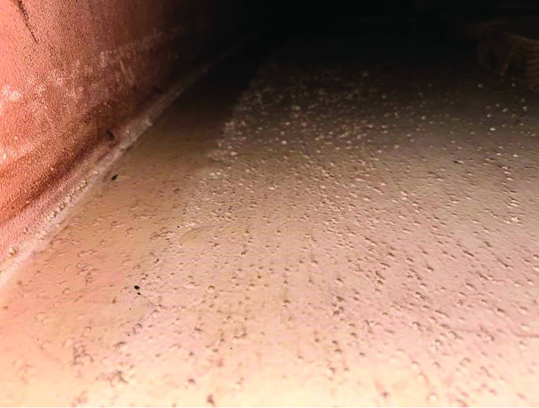
Many lining defects present as blisters, pinholes, delamination, cracking, or rapid underfilm corrosion. These symptoms often have different root causes but are frequently linked by the same main underlying mechanisms:

  • Cure inhibition or solvent entrapment caused by low
    temperatures, poor ventilation, excessive film build or incompatible overcoating windows.
  • Incompatibility with internal cathodic protection (where fitted).
  • Osmotic blistering where soluble contaminants (for example, chlorides or sulphates) draw water through the coating and form blisters.
  • Permeation and chemical attack when a lining is not selected for the actual service conditions (including temperature and vapour phase exposure).
  • Poor surface preparation and uneven weld profiles.
  • Deterioration of the cleanliness standard between blasting and coating application.
  • Underfilm corrosion driven by retained salts, moisture, or poor surface preparation that leaves active corrosion sites.

Photo: Lining Blisters

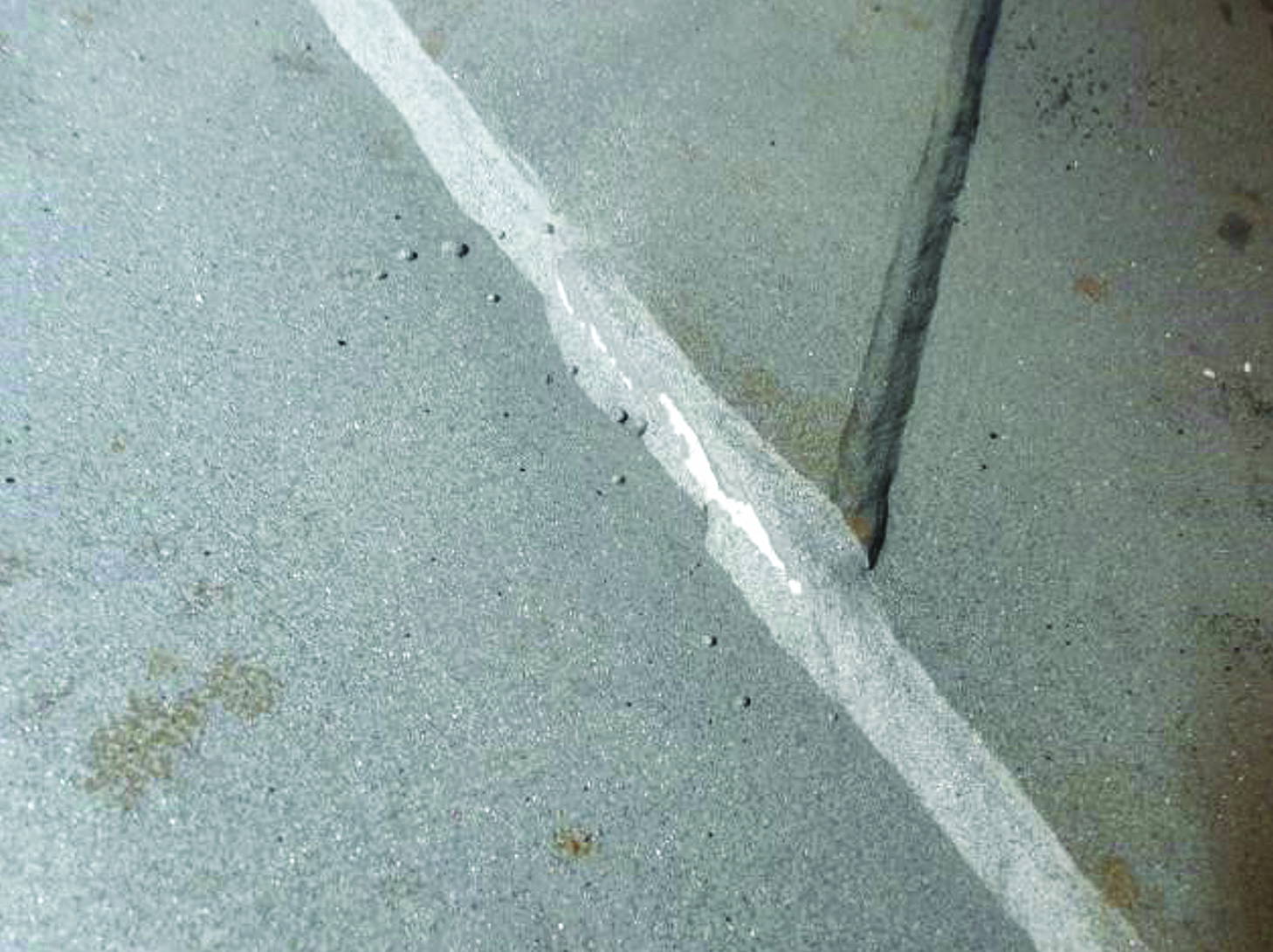
Photo 2: Showing Weld Defects, Substrate Contamination, Gingering on Tank Floor Plates.

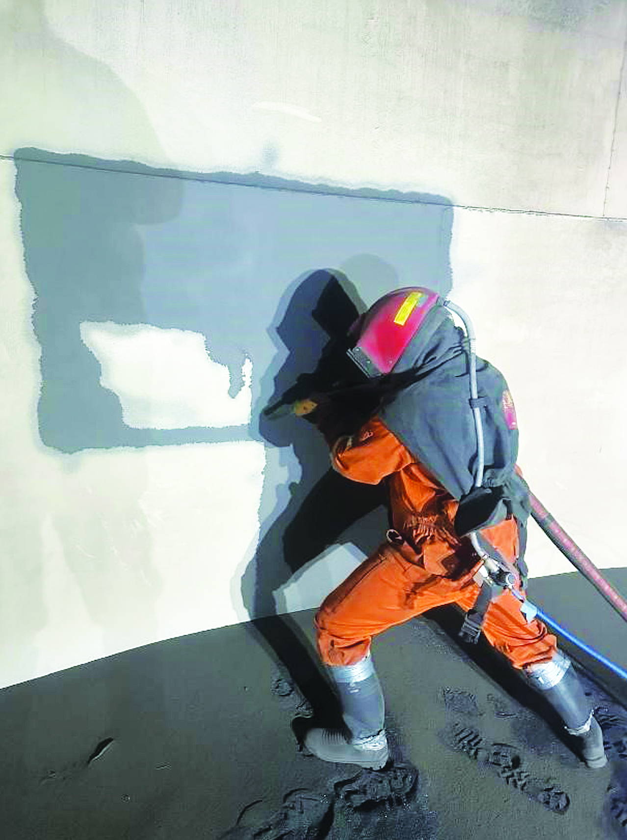
Photo 3: Removal of the Lining and Preparation of the Steel Surface to ISO 8501-1 Sa2½.

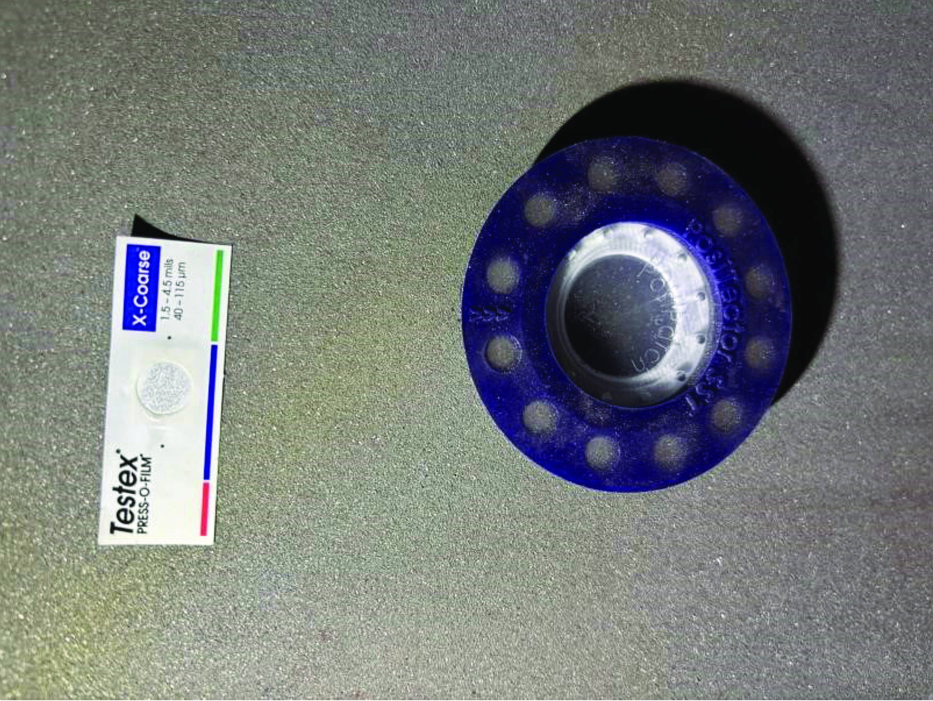
Photo 4: Inspection of the Substrate Being Carried Out to Determine Soluble Salt Contamination (ISO 8502-6/9) and Surface Profile (ISO 8503).

Understanding these mechanisms helps teams focus on controllable parameters and hold points rather than treating defects as isolated events.

Additional Considerations for Specification and Risk Ownership

Beyond workmanship, the lining system is influenced by decisions made at the project design stage: specification, preparation philosophy, access and ventilation design, inspection scope, and commissioning constraints. High-performing projects treat lining installation as a managed engineering activity with defined acceptance criteria, rather than a “paint job” executed at the end of a shutdown.

A useful way to think about internal linings is to regard them as a barrier system with known limits. If the service environment, application conditions, or commissioning regime exceed those limits, failure becomes a matter of time rather than chance. The prevention measures that follow are therefore centred on controlling the few variables that matter most: service fit, cleanliness (including salts), environment, thickness, cure, and verification.

Two practical habits consistently separate reliable outcomes from repeat failures. Firstly, teams agree on the acceptance criteria before mobilisation — including where measurements will be taken, how many will be taken, and what constitutes a pass or fail. Secondly, they treat deviations as decisions, not inconveniences. If salt levels exceed the agreed threshold, the response is defined: re-clean, retest, and do not coat. If the dew point margin is not maintained, work stops. This clarity removes ‘’on-the-day’ debate and prevents schedule pressure from quietly overriding engineering controls.

Where possible, owners should also align lining work with a simple quality assurance risk register. For each major risk (contamination, condensation, over-build, incomplete cure, discontinuities), define the prevention control, the verification method, and the evidence required for sign-off. This approach makes lining projects easier to manage and far easier to defend when incidents, disputes, or warranty discussions arise.

Vapour Space Versus Immersion Exposure

A frequent source of surprise is vapour phase corrosion and attack. Condensation cycles, oxygen availability, and elevated temperatures can create a more aggressive environment in the vapour space than in the liquid phase. Where tanks store fuels, solvents, or chemicals with fluctuating levels, the splash zone and vapour space should be assessed explicitly. In some cases, a dual-system specification (or additional stripe coats / reinforcement in the vapour space) provides better reliability than a single uniform build.

It is also important to consider operational transients: hot fills, cold ambient periods, steam cleaning, or CIP chemicals. Lining selection should account for credible upset conditions, not only normal operation.

Acceptance Criteria and Measurement Methods

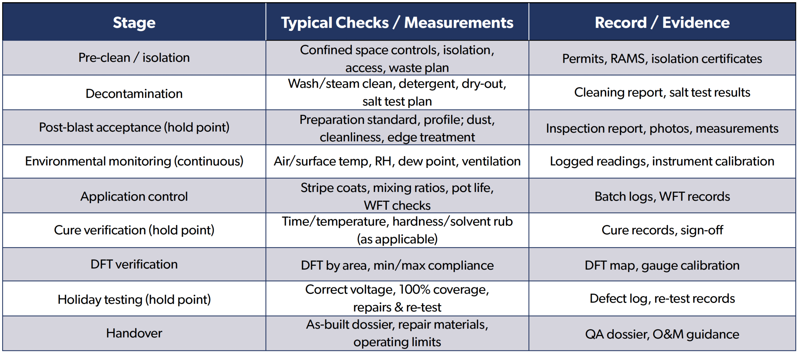
To reduce ambiguity, projects should define how compliance will be measured. Common controls include:

  • • Environmental readings recorded at set intervals and whenever conditions change.
  • Holiday testing with documented voltage, coverage, defect log, repair and re-testing.
  • Soluble salt levels measured using the Bresle method (ISO 8502-6/9).
  • Surface profile measured with replica tape or needle gauge.
  • Wet film thickness (WFT) checks during application and dry film thickness (DFT) verification after cure.

While accurate and timeline reporting can be deprioritised by programme pressure, it ensures that issues are discovered early, while correction is still practical. It also provides auditable and defensible evidence to demonstrate compliance and protect the parties involved in the event of any future claim.

Typical Failure Signatures

Inspectors often encounter repeatable “signatures” that point to root cause:

  • • Cracking, which can result from over-build, thermal cycling or substrate movement.
  • Large blisters or broad delamination may indicate condensation, poor adhesion or incompatibility.
  • Pinholes and rust spots are commonly linked to inadequate stripe coating, air entrapment or ineffective holiday testing.
  • Small, high-density blisters often correlate with soluble salt contamination.
  • A soft or easily damaged film suggests incomplete cure or incorrect mixing ratios.

Capturing these observations during inspection supports faster diagnosis and more targeted corrective action.

Prevention Measures

1. Incorrect Lining Selection for the Service Environment Selecting a lining based on price, familiarity, or generic data rather than on verified resistance to the specific stored product, contaminants, temperature range, and operating regime (including vapour space exposure) is a leading cause of premature failure.

Prevention Measures

  • Assess both immersion and vapour phase exposure as the vapour space can be more aggressive than immersion.
  • Confirm the stored media, concentration, operating temperature, cleaning chemicals, and any process upset conditions.
  • Specify system build (primer/intermediate/topcoat), DFT range and cure requirements for the service.
  • Use manufacturer chemical resistance data for the exact product and temperature, and verify it with independent guidance where appropriate.

2. Inadequate Surface Preparation (Profile, Cleanliness, and Degree of Preparation)

Even high-performance linings cannot compensate for inadequate surface preparation. Insufficient cleaning or an incorrect profile reduces adhesion and increases the likelihood of underfilm corrosion and delamination.

Prevention Measures

  • Confirm that sharp edges are treated and that all weld spatter is removed.
  • Ensure all critical areas receive a thorough stripe coat, ensuring sufficient coverage.
  • Define the required preparation standard (e.g., Sa 2½ / SSPC-SP10) and the target profile range appropriate to the system.
  • Hold point: do not proceed to coating until preparation has been verified and recorded.
  • Inspect for shadows, tight corners, and complex welds that may need additional preparation.

3. Soluble Salt Contamination (Chlorides, Sulphates, Nitrates)

Soluble salts are a common hidden contributor to osmotic blistering and rapid underfilm corrosion. Salts can originate from stored product residues, marine environments, process contamination, or abrasive and water sources.

Prevention Measures

  • Control abrasive quality and avoid the use of recycled abrasive that can introduce contaminants.
  • Document test locations and results as part of the QA dossier.
  • Include salt testing in the inspection plan (e.g., Bresle method) with acceptance criteria agreed pre-job.
  • Use effective decontamination (fresh-water washing, steam cleaning, detergents) and re-test to confirm removal.

Poor Environmental Control During Application (Dew Point, Humidity, Temperature)

Applying linings outside specified environmental limits can cause condensation, amine blush, pinholing, poor cure, and reduced adhesion. Small excursions are often enough to create defects that only appear after commissioning.

Prevention Measures

  • Maintain the specified surface temperature margin above the dew point (commonly >3°C, unless stated otherwise).
  • Monitor steel temperature, air temperature, relative humidity, and the dew point throughout the shift.
  • Stop work when limits are exceeded and resume only once conditions are stable and recorded. 
  • Use dehumidification, heating, and forced ventilation where necessary — especially in enclosed tanks. This includes during overnight cure where required.

5. Incorrect Film Thickness (Under-Build or Over-Build)

Film thickness is a controlled parameter. Under-build reduces barrier performance, while over-build increases the risk of solvent entrapment, cracking, and cure issues — particularly in high build epoxies.

Prevention Measures

  • Investigate and correct systematic thickness deviations rather than
    “averaging them out”.
  • Specify minimum and maximum DFT per coat and for the total system; align with manufacturer guidance.
  • Treat complex geometry as higher risk and plan additional stripe coats.
  • Use WFT gauges during application and DFT measurements after cure; record results by area.

6. Poor Workmanship at Critical Details (Edges, Welds, Terminations, Nozzles)

Edges, welds, and terminations are stress concentrators and common initiation points for coating breakdown due to thin film build and mechanical damage.

Prevention Measures

  • Inspect details at hold points before full coat application.
  • Protect terminations and consider reinforcement where appropriate (e.g glass flake or fabric reinforcement).
  • Specify edge grinding/radius requirements and stripe coats
    on all edges, welds and cut-outs.
  • Use appropriate application methods to achieve target build on details (brush/roller stripe coats).

7. Inadequate Cure and Commissioning Control

Many failures are linked to lining systems being placed into service before they have achieved adequate cure. This is particularly prevalent in cold climates, under time pressure, or where ventilation is poor.

Prevention Measures

  • Define cure criteria (time/temperature, hardness, solvent resistance) before the job starts.
  • Do not introduce product, water, or cleaning chemicals until cure acceptance is formally signed off.
  • Ensure ventilation is adequate to remove solvents and support cure, especially in deep tanks. 
  • Verify cure using appropriate methods (e.g., solvent rub/MEK where applicable, hardness checks) in line with manufacturer guidance.

8. Holiday Testing Gaps and Ineffective Defect Repair

Pinholes and discontinuities allow rapid underfilm corrosion. Holiday testing is only effective when voltage selection, inspection coverage and repair methods are correct.

Prevention Measures

  • Ensure testing covers welds, terminations, and complex areas where discontinuities are more likely.
  • Include holiday testing as a formal hold point with correct equipment calibration and voltage selection.
  • Maintain a defect log with locations, repair details, and re-test results.
  • Mark defects clearly, repair in accordance with manufacturer guidance, and re-test repaired areas.

9. Inadequate QA/Inspection Hold Points and Documentation

It is essential that Quality Assurance (QA) hold points are enforced, otherwise defects are often ‘built in’ and only discovered late — when correction is costly or impractical.

Prevention Measures

  • Define acceptance criteria for preparation, salts, environmental conditions, WFT/DFT, cure, and holiday testing.
  • Ensure responsibilities are clear for all parties (asset owner, inspector, contractor) and records are retained.
  • Implement a documented Inspection and Test Plan (ITP) with clear hold/witness points.
  • Treat the QA dossier as part of the asset record, supporting future inspections and repairs.

10. Post-Handover Operational Factors (Mechanical Damage, Cleaning, Temperature Excursions and Water Bottoms)

Even a well-installed lining can fail early if operating conditions exceed design assumptions. Common issues include aggressive cleaning, unexpected chemical exposure, thermal cycling, prolonged water bottoms, and poor housekeeping leading to microbiological activity.

Prevention measures

  • Document operating limits, cleaning restrictions, and compatible repair materials.
  • Ensure repairs are compatible, controlled, and re-tested (including holiday testing).
  • Monitor for water bottoms, sludge accumulation and microbial activity where relevant.
  • Plan routine internal inspections and address minor defects early.

A Practical Vignette: Avoiding a “Perfect Storm” Failure

Consider a shutdown where the tank is cleaned and blasted late in the programme. The abrasive quality is acceptable, but soluble salts are not verified and environmental readings are taken only at the start of the shift. Overnight temperatures drop and the steel temperature approaches the dew point. The next morning, coating proceeds to maintain the schedule, resulting in intermittent condensation in shadowed areas. Film thickness is locally high on welds due to repeated stripe coats, and cure is assumed to be complete after a nominal time period.

The lining initially appears satisfactory, but blisters and rust spots develop within months of commissioning. In many cases, the root cause is not a single major error, but a chain of small misses: no salt verification, inadequate environmental control, over-build at edgework, and insufficient cure verification. Breaking any one link — for example, enforcing a hold point for salt testing or maintaining a strict dew point margin — can prevent the failure entirely. This illustrates why systematic hold points and evidence-based acceptance criteria are more reliable than relying on experience and good intentions alone.

Key lessons from this type of scenario are straightforward: establish measurable hold points early, keep environmental control equipment available and properly sized, avoid exceeding maximum film build on details, and verify cure with an agreed method rather than relying on time alone. When these controls are in place, the project team can move quickly with confidence — and when they are not, the apparent time saved is usually paid back many times over in rework and premature failure.

Asset Owner Risk Control

A lining should be treated as part of the wider asset management system — not as a one-off project. Owners can significantly reduce risk by ensuring that the specification is fit for purpose, enforcing hold points, and maintaining operational discipline after handover.

Practically, this means budgeting for the controls that prevent rework: time for decontamination and re-testing, provision for dehumidification and ventilation, access that allows proper inspection coverage, and a commissioning plan that does not force early immersion. The cost of these controls is typically small compared with the cost of early failure, product contamination, unplanned shutdowns, and repeat lining campaigns.

The Asset Owner’s Risk Management Checklist

  • Correct lining selection for service (immersion and vapour)
  • Surface preparation and salt control embedded in the ITP
  • Environmental control during application (dew point margin maintained)
  • Film thickness controlled within stated min/max limits
  • Cure verification before exposure to service
  • Defined hold points and documented QA dossier
  • Holiday testing completed, defects repaired and re-tested
  • Post-handover operating limits and cleaning restrictions documented
  • Planned inspection intervals and compatible repair strategy.

Conclusions

Many internal lining failures are considered avoidable. When teams manage risk deliberately — by controlling preparation, contamination, environment, thickness, cure, and post-handover operation — service life becomes far more predictable and total cost of ownership reduces. Ultimately, the difference between a lining that lasts and one that fails early is rarely the coating brand. It is the discipline of specification, verification, and decision-making at hold points. If the project team can answer “yes” to the key questions — Is the system proven for service?
Is the steel clean (including salts)? Are conditions controlled?
Is the thickness within limits? Is cure verified? Is the lining continuous? — then failure risk drops dramatically. Where QA hold points are not enforced, defects are often “built in” and only discovered when it is too late.

References

1. ISO 8501-1, Preparation of steel substrates before application of paints and related products — Visual assessment of
surface cleanliness.

2. AMPP SP 10/NACE No. 2, Near-White Metal Blast Cleaning.

3. ISO 8502-6, Preparation of steel substrates before application of paints and related products — Tests for the assessment of surface cleanliness — Part 6: Extraction of soluble contaminants for analysis — Bresle method.

4. ISO 8502-9, Preparation of steel substrates before application of paints and related products — Tests for the assessment of surface cleanliness — Part 9: Field method for the conductometric determination of water-soluble salts.

5. ISO 8502-3, Preparation of steel substrates before application of paints and related products — Tests for the assessment of surface cleanliness — Part 3: Assessment of dust on steel surfaces prepared for painting (pressure-sensitive tape method).

6. AMPP SP0188, Discontinuity (Holiday) Testing of New Protective Coatings on Conductive Substrates.

7. ISO 8503, Preparation of steel substrates before application of paints and related products — Surface roughness characteristics of blast-cleaned steel substrates.

ICorr President Attends the 1st China Cathodic Protection Conference in Qingdao

ICorr President Attends the 1st China Cathodic Protection Conference in Qingdao

19–20 September 2026 | Qingdao, China

The President of the Institute of Corrosion (ICorr), Dr Yunnan Gao, attended the 1st China Cathodic Protection Conference, held in Qingdao, China, from 19–20 September 2026, at the invitation of Professor Xiaogang Li, President of the Chinese Society for Corrosion and Protection (CSCP).

Organised by the Cathodic Protection Technical Committee of the CSCP, the conference was the first national conference in China dedicated specifically to cathodic protection. The event attracted around 500 delegates from China and overseas, bringing together experts, researchers, engineers, manufacturers, operators and other professionals from across the cathodic protection community.

The two-day programme combined a half-day plenary session, a full day of parallel technical sessions covering a broad range of cathodic protection topics, an exhibition showcasing relevant technologies and products, and a half-day programme of industrial visits to leading organisations in the field.

For ICorr, the conference provided an important opportunity to contribute to the opening ceremony, exchange technical knowledge with the Chinese and international corrosion community, engage directly with industry, and advance the high-level professional dialogue between ICorr and CSCP.

A Major National Forum for Cathodic Protection

The two-day programme combined a plenary conference, parallel technical sessions, a technology and product exhibition, and industrial visits.

The opening programme on 19 September included the conference opening ceremony, the release of the Cathodic Protection Industry Development Report, recognition of leading professionals in the field, and plenary technical presentations. This was followed by parallel sessions addressing specialist areas of cathodic protection, including pipeline cathodic protection, cathodic protection in marine environments, nuclear power and bridge applications, and underground pipeline networks.

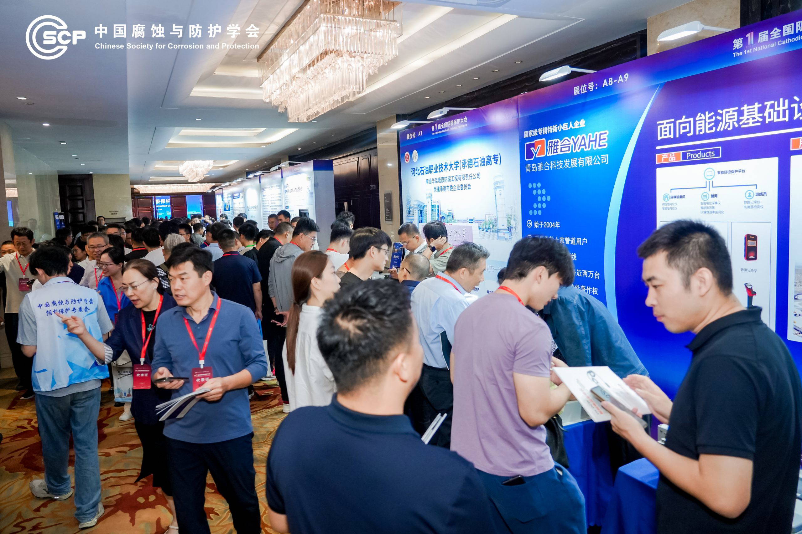
The conference also featured an extensive exhibition showcasing cathodic protection materials and equipment, monitoring technologies, testing and inspection instruments, digital management platforms and associated engineering solutions.

The final afternoon was dedicated to technical and industrial visits, giving delegates with an opportunity to observe cathodic protection and corrosion-control technologies in practical applications.

ICorr Representation at the Conference

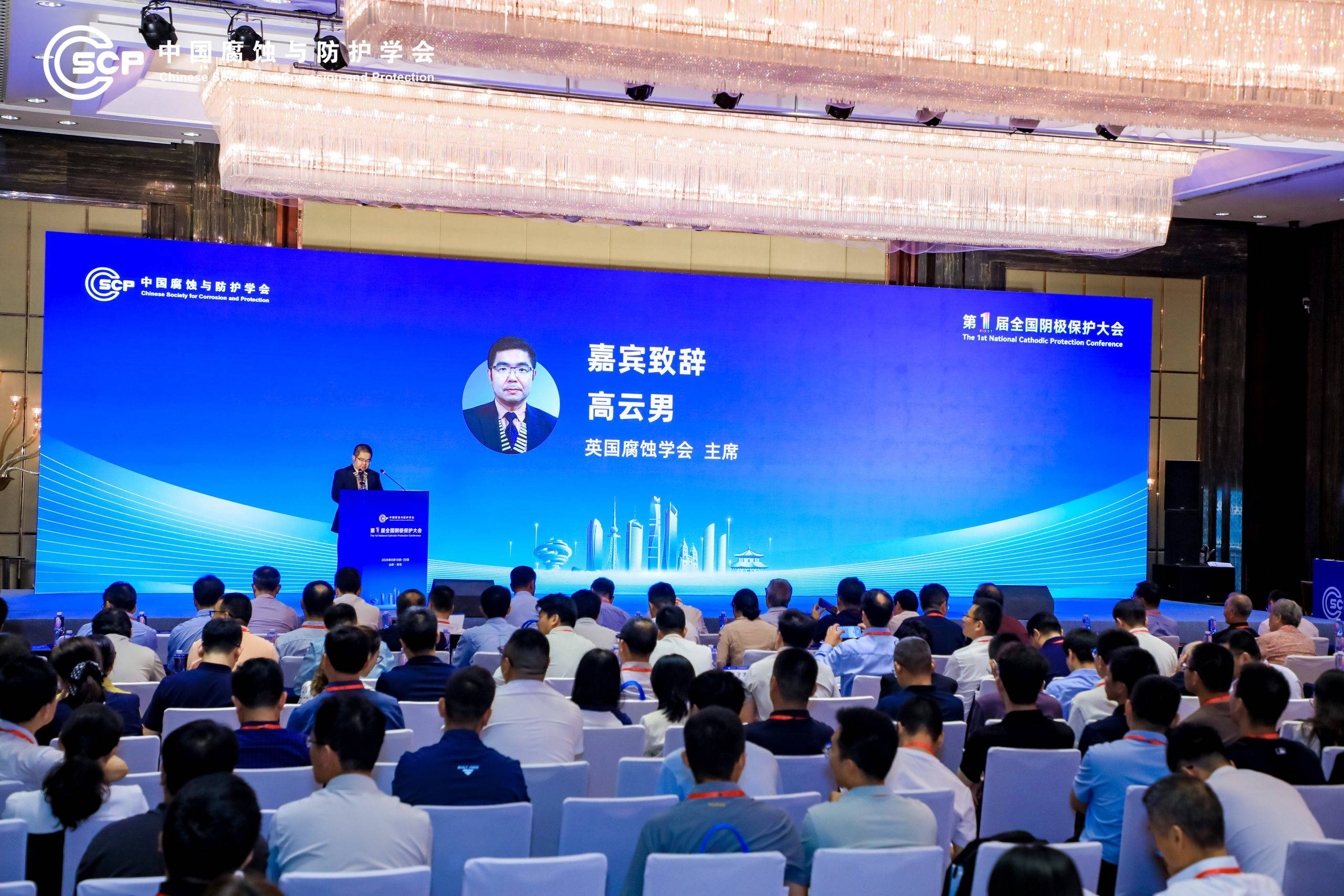
Dr Yunnan Gao represented ICorr throughout the conference programme. He attended the opening ceremony and delivered an invited address, representing ICorr and highlighting the importance of international professional cooperation in advancing corrosion science and engineering.

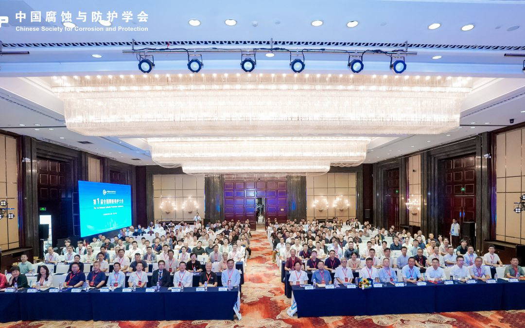
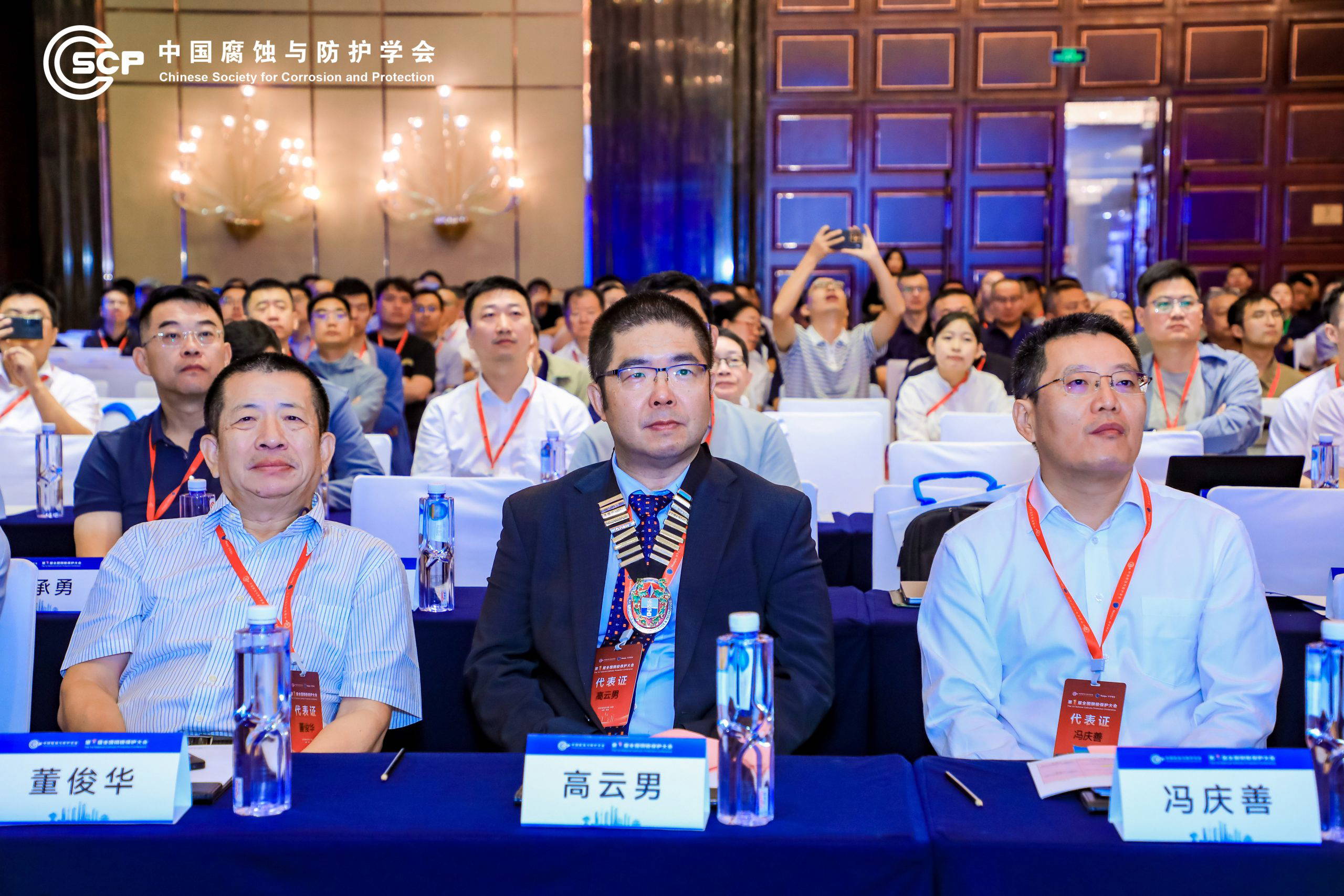
Photo 2 – Dr Yunnan Gao, President of ICorr, seated at the centre, attends the opening ceremony of the 1st China Cathodic Protection Conference.

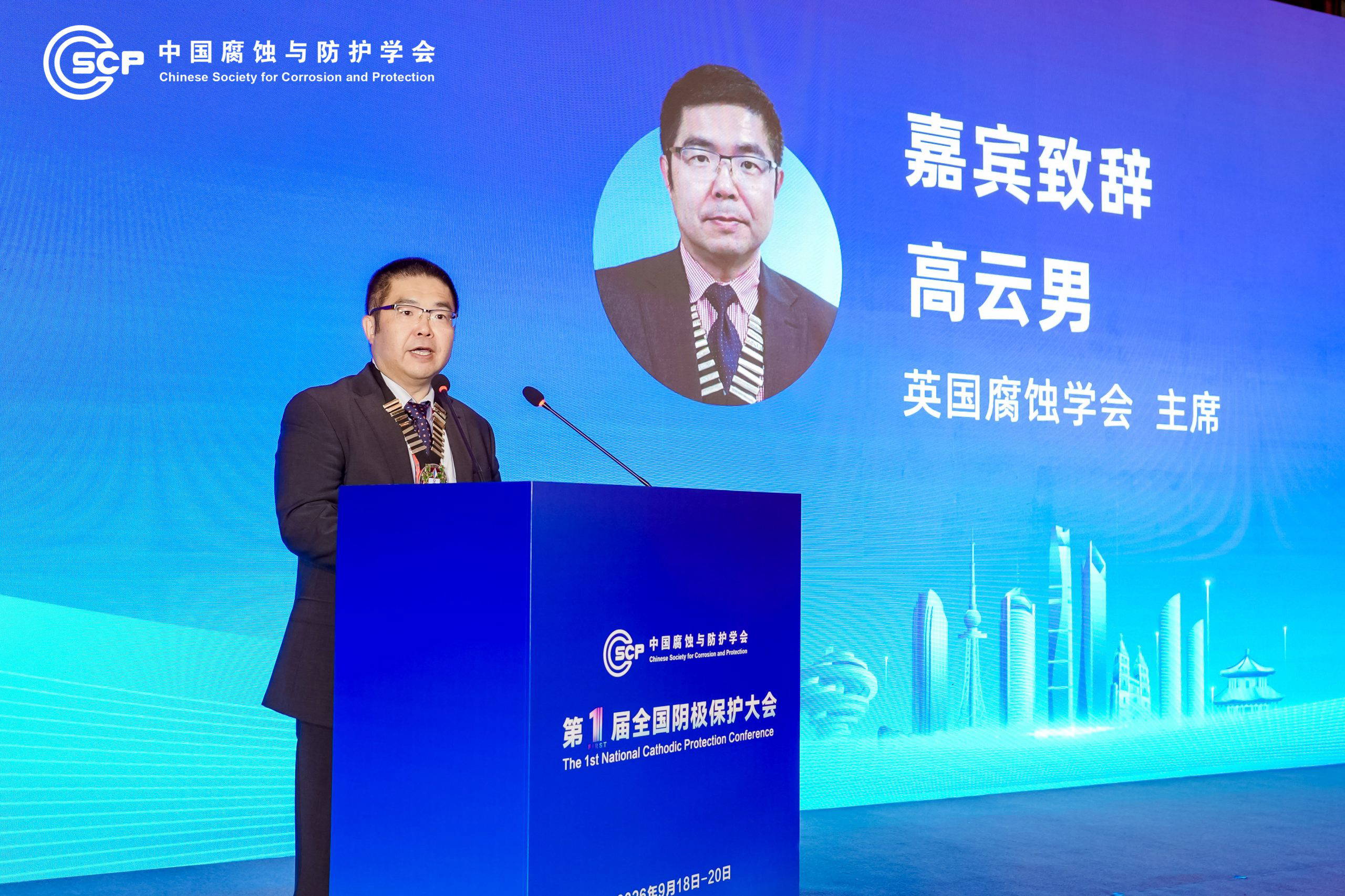
Photo 3 – Dr Yunnan Gao addresses delegates during the opening ceremony, on behalf of ICorr.

Photo 4 – ICorr President Dr Yunnan Gao delivers his opening address to the conference.

During the conference, Dr Gao attended the plenary presentations and technical sessions, exchanging knowledge with specialists from across the breadth of cathodic protection field.

The technical programme reflected the increasingly multidisciplinary nature of modern cathodic protection. Topics included system design and optimisation, lifecycle management, effective testing and evaluation, new anode and reference-electrode materials, remote monitoring and intelligent management, stray-current interference, and practical experience in engineering design, construction and operation.

 Engagement with Industry and Technology Exhibitors

The conference exhibition provided an important opportunity for ICorr to engage directly with companies developing and applying cathodic protection technologies in China.

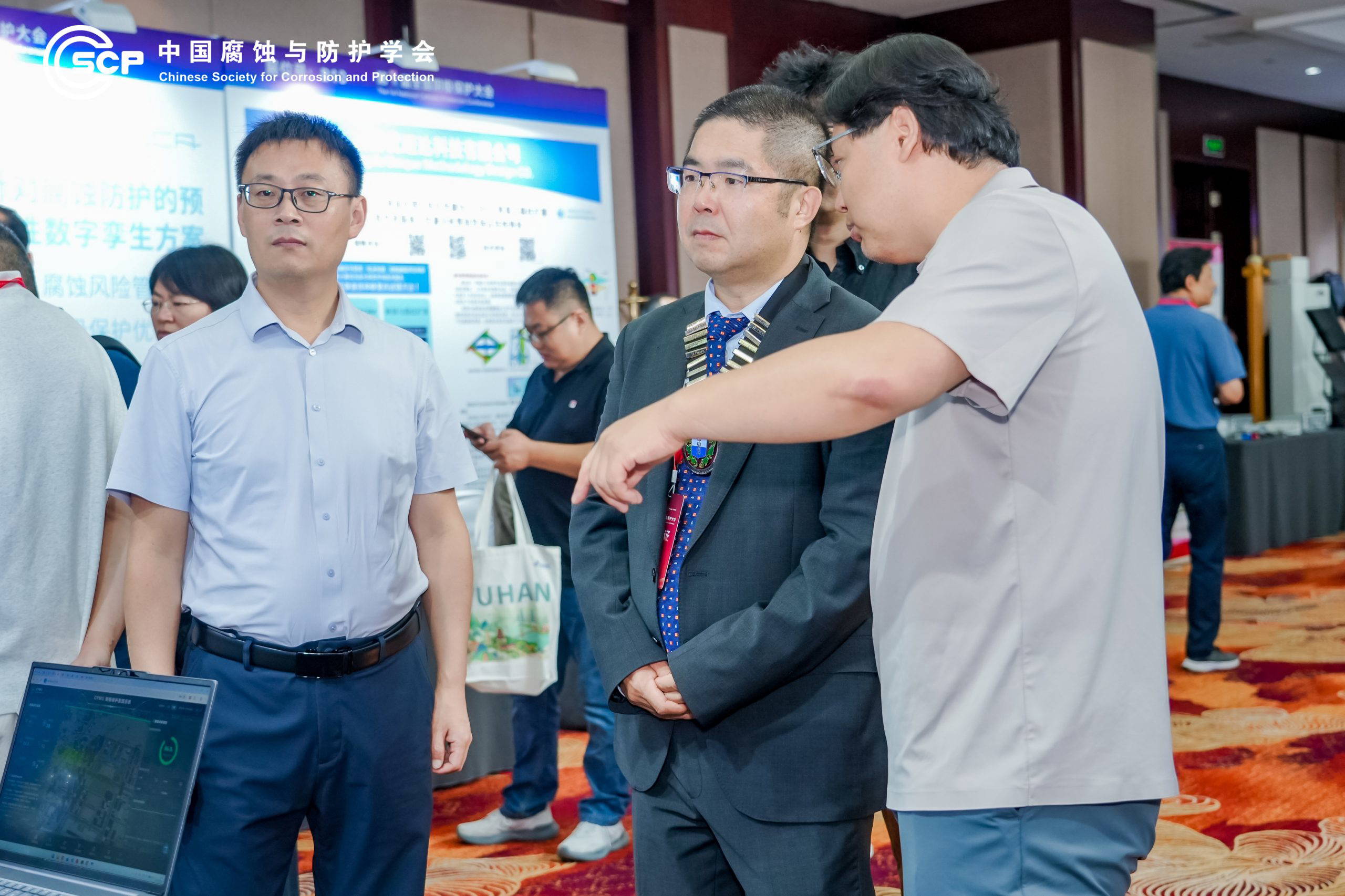
Dr Gao visited exhibition stands, discussed technologies and applications with exhibitors, and exchanged views with professionals involved in cathodic protection equipment, materials, monitoring, testing and engineering services.

Photo 5 Delegates and industry professionals engage with exhibitors during the cathodic protection technology and product exhibition.

Photo 6 Dr Yunnan Gao exchanges technical views with an exhibitor during the conference exhibition.

The direct engagement provided useful insight into the developments in China’s cathodic protection sector and created further opportunities for professional and technical exchange between ICorr and the wider Chinese corrosion community.

Industrial Visits: Connecting Technology with Application

The conference programme concluded with visits to leading organisations involved in corrosion and cathodic protection technologies.

The visits provided delegates with an opportunity to see large-scale corrosion testing and engineering capabilities in practical environments, complementing the technical discussions held during the conference.

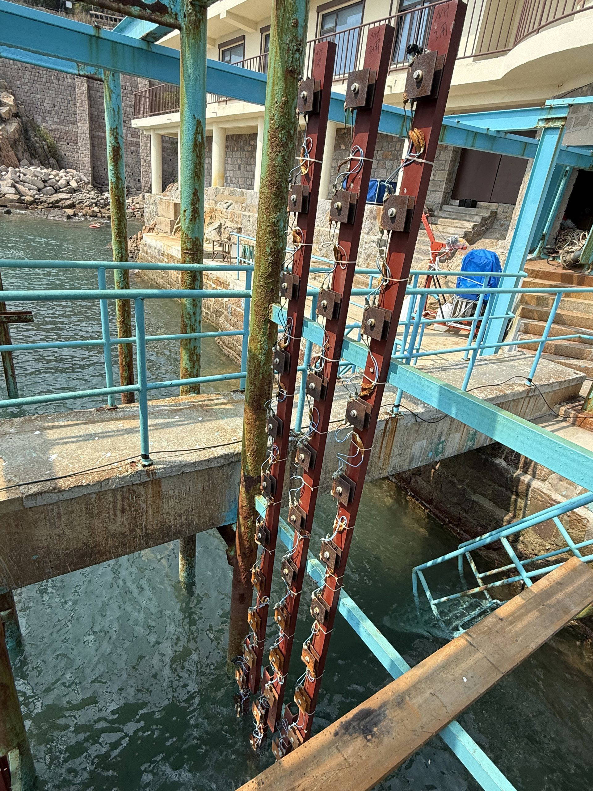
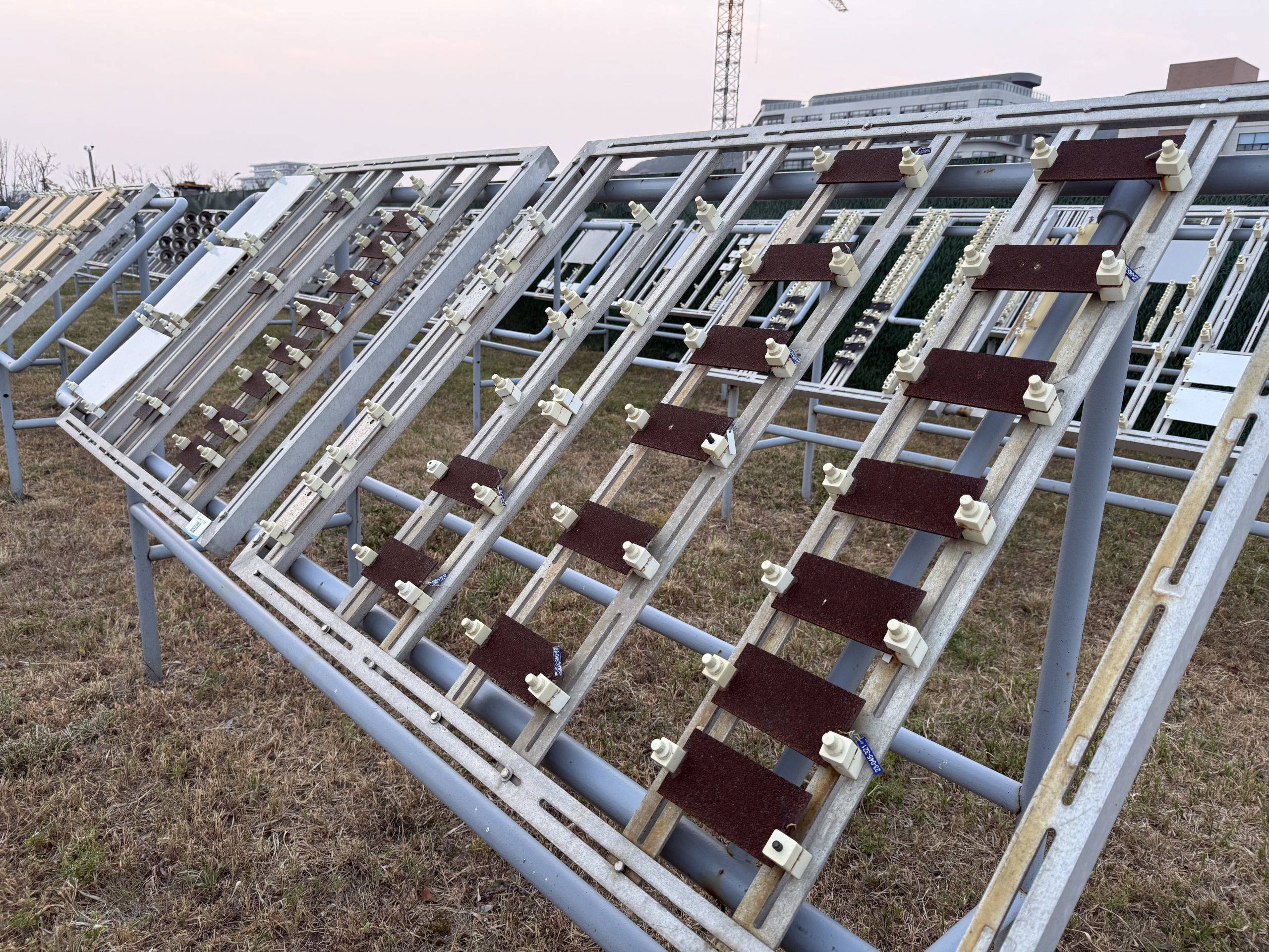
Among the facilities visited were large-scale testing capabilities using natural seawater and atmospheric corrosion testing under natural marine environmental conditions.


Photo 7 – Delegates examine full-scale corrosion testing facilities using natural seawater during the industrial visit.

Photo 8 – Delegates visit full-scale atmospheric corrosion testing facilities in a natural marine environment.

These visits were particularly valuable in demonstrating the connection between laboratory research, environmental exposure testing, technology development and practical engineering application.

Continuing ICorr–CSCP Collaboration

The conference also provided an important opportunity to continue the dialogue between ICorr and CSCP.

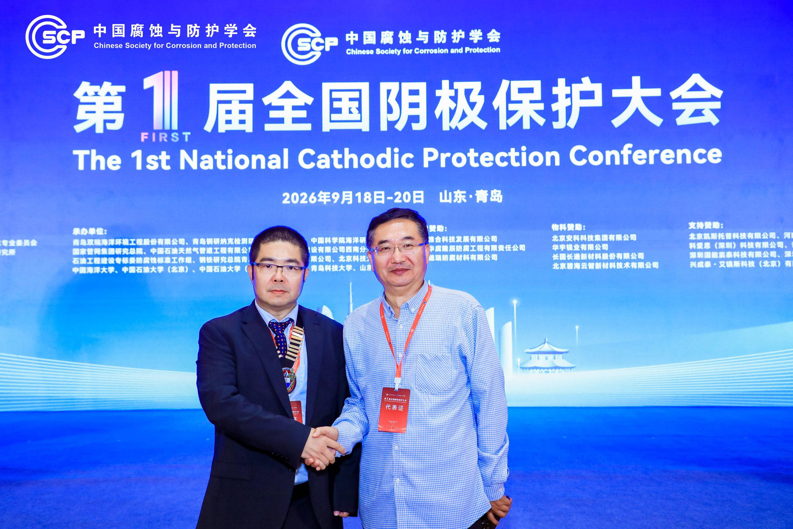
Dr Gao held further high-level discussions with Professor Xiaogang Li, President of CSCP, continuing the close professional dialogue and collaboration between the two organisations.

These discussions supported the continuing relationship between ICorr and CSCP, with both organisations sharing a strong commitment to professional development, technical knowledge exchange and international cooperation in corrosion science and engineering.


Photo 9 Dr Yunnan Gao, President of ICorr, and Professor Xiaogang Li, President of CSCP, continue discussions on professional and technical collaboration.

The relationship between ICorr and CSCP has developed significantly in recent years, with cooperation encompassing professional exchanges, conferences, technical activities and wider engagement between the corrosion communities in the UK and China.

Supporting International Exchange in Cathodic Protection

The successful inaugural China Cathodic Protection Conference represents an important development for China’s cathodic protection community in China. Its combination of scientific and engineering presentations, an industry exhibition and practical industrial visits provided a comprehensive platform for knowledge exchange across the sector.

For ICorr, participation in the conference provided an opportunity not only to contribute to the opening programme, but also to learn about recent technical developments, engage with practitioners and technology providers, and strengthen professional relationships across the China’s corrosion and cathodic protection community.

ICorr looks forward to continuing its engagement with CSCP and with colleagues throughout China, supporting the international exchange of knowledge and experience in corrosion prevention, cathodic protection and asset integrity internationally.

The Institute congratulates CSCP and all the organising and supporting organisations on the successful delivery of this inaugural national cathodic protection conference.