

Fellow’s Corner

Fellow’s Corner

Overcoming Plant Isolation Issues within Cathodic Protection Design

Dr Ahmed Mahgoub, FICorr

Dr Ahmed Mahgoub is cathodic protection subject matter expert for Saudi Arabian Oil Company (Saudi Aramco) in Dhahran, Saudi Arabia. He has more than 19 years of experience in the consulting, engineering, constructing and commissioning of different cathodic protection structures. He is a an AMPP CP Specialist, ICorr CP specialist, Fellow of ICorr, ICorr CPGB Member and AMPP Snr. Corrosion Technologist.

Introduction

Cathodic protection (CP), when applied properly, is an effective means to prevent corrosion of underground plant piping. For many underground applications, such as pipelines, CP system design is relatively straightforward. Plant and facility environments, however, are not simple applications. Plants have congested underground piping systems such as process drains and other utilities in a tightly spaced footprint. The presence of copper grounding systems, foundations with reinforcing steel embedded in concrete, conduit, utility piping and structural pilings (either bare or concrete with reinforcing steel) can greatly complicate the task of designing a pipe CP system.

For simple plant facilities, it is possible to isolate the piping and utilise a conventional galvanic corrosion prevention system. This works only if the plant piping is electrically isolated from other underground structures for the life of the facility. For most plant and facility applications, it is not practical to isolate the piping from the grounding system for the life of the facility. In these cases, an impressed current cathodic protection (ICCP) anode system is the only alternative as a galvanic system does not normally have sufficient capacity to overcome plant earth connections. This paper represents the linear mixed metal oxide (MMO) anodes, which in suitable conditions can be an optimal method of providing adequate CP protection criteria as specified in [1-4] to the piping network in crowded areas of oil and gas plants.There are two conventional approaches to cathodically protecting underground plant piping using impressed current anodes – deep vertical anode bed and shallow / distributed anode bed. However, there are three principal industry challenges to consider for any CP system within a plant and described as shortages in utilising a conventional ICCP system.

  • First is the current distribution issue due to highly congested underground environment that is common to most plants.
  • The second critical factor is isolation in the presence of a pervasive copper grounding network, often applied for safety reasons to protect rotating equipment and security fences.
  • Third is the probability of DC interference due to stray currents from multiple sources.
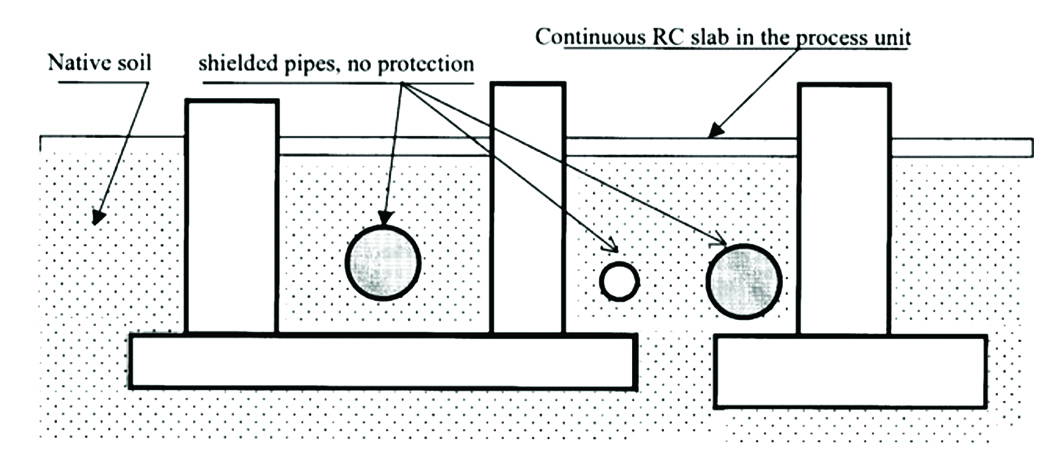
Figure1: A Typical Process Piping Layout Where Reinforced Concrete Foundations are Restricting The Flow of Protective Current.

MMO System

The linear MMO Anode is a long-line, flexible, cable-like anode, which is placed in continuous close proximity to (typically 0.5m to 1m from) the piping network. In conditions of similar backfill/resistivity, uniform distribution of CP current is therefore achieved on applications where many conventional anodes ground beds do not work or would cause excessive interference. In contrast to conventional anode ground beds CP systems, Linear MMO Anode is placed in the ground parallel and in close proximity to the plant piping to be protected and provides uniform distribution of protective current to the entire steel surface as demonstrated in various studies [4-9], thereby maintaining the steel-to-soil “instant-off” potential in the required protection criteria.
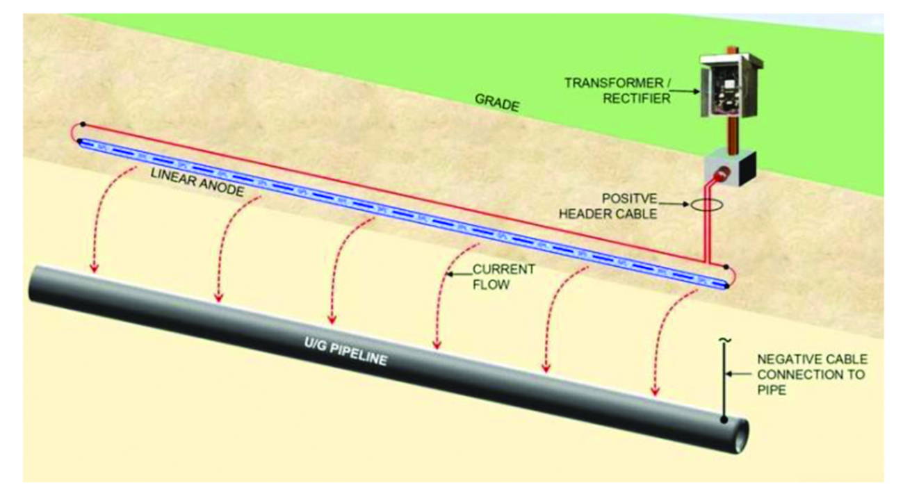


Figure 2: UG Pipeline CP System with Single Linear Anode Layout.

Backfilled Linear Anode

The MMO based anode represents the second generation of backfilled linear anodes. The platinum based catalytic anodes were quickly replaced with MMO based wire anodes as they were more cost effective, less prone to failure, allowed for a longer anode system life and a larger range of current outputs, and provided a far more robust material.
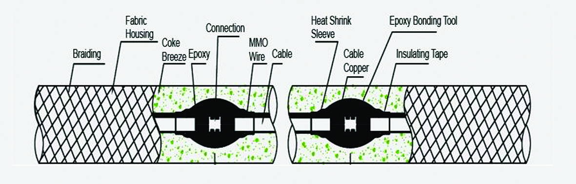
Figure3: MMO Linear Anode Composition.

Below are the key elements that contribute to the MMO linear anode composition,

  • Core, is crafted from high-quality titanium wire. This core is meticulously coated with a catalyst blend derived from Mixed Metal Oxides, predominantly featuring Iridium and Tantalum
  • MMO Coating, on one hand incorporates an electrocatalytic conductive element, which acts as a catalyst to drive the essential reactions for current generation. On the other, it embeds bulk oxides that serve as a protective shield, ensuring the substrate material remains resistant to corrosion.
  • Acid Resistance Fabric, this fabric is designed to provide an additional layer of protection against acidic environments. Its unique composition ensures that the MMO linear anode remains safeguarded from potential corrosive effects of acids, thus enhancing its longevity.
  • Protective Braid, surrounding the anode is a protective braid which offers mechanical protection. This robust braid ensures that the anode is shielded from external wear and tear, making it more durable and resilient to external forces.
  • Coke Breeze is a common backfill material for ICCP systems. It not only enhances the conductivity of the anode but also aids in distributing the current This ensures efficient operation and reduces potential hot spots.

The MMO linear anode functions as a distributed system including an infinite number of continuously spaced anodes. This system offers the optimal technical CP solution while minimising the required current output as detailed below:

  • Electrical isolation is not necessary, Because the MMO linear anodec is closely located next to the piping being protected, electrical isolation as illustrated in [4] is not a significant concern. The anode is “closely coupled” to the piping and operates with a very low anode gradient that minimises any losses to nearby structures including grounding equipment.
  • Maintains uniform current distribution by positioning the anode parallel and in very close proximity to the piping being protected, the linear anode CP system design eliminates any requirement for supplemental anodes to address areas where remote anodes may be shielded after the CP system is commissioned. Wherever the piping goes, the linear anode follows in the same trench. This also makes it very easy to adapt the design during piping revisions that may change the piping system routing as the plant construction Sufficient care must be taken during its installation of course.
  • Elimination of stray current risks, close proximity to the piping being protected significantly limits current losses to other structures and virtually eliminates shielding and stray current This also significantly reduces the total current requirements for the system, reducing the rectifier requirements.
  • Access restrictions, the MMO linear anode is installed in very close proximity to the piping that is to be protected. This minimises the risk of third-party damage and reduces trenching required for buried cable and drilling required for distributed anodes. If installed in conjunction with the piping, the anode can be placed in the same trench as the piping affording the anode protection by the piping itself from external damage. This is a very cost-effective CP installation when installed concurrently with the piping and to correct spacing.
  • Ease of installation, when installed alongside the piping during pipelay a matter of laying the anode cable in the trench with no further drilling is needed.

Case Study

  • This section outlines the proposed CP system by linear MMO anodes for new 8” & 6” underground Header and branch underground piping’s network in Saudia The total length of the gas grid distribution piping network in this instance is 4900m and the piping will be protected by a permanent (ICCP) system for a lifetime of (25 years) according to project specifications by applying a new CP system of 25V/15A rating.
  • The MMO Linear Anodes comprise a continuous MMO/Ti wire with copper cable packaged in fabric jacket fulfilled with calcinated coke installed parallel to the pipelines in the same trenches by maintaining a minimum distance of 0.5-0.8m from pipeline.
  • A header cable is attached at the factory via a high-pressure crimp connector to ensure a low resistance That connection is then sealed in a splice kit with epoxy resin to prevent water intrusion.
  • Finally, the header cable to anode feeder cable connection is performed on site as per the manufacture specification and standard
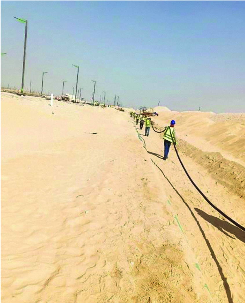
Figure 4: Installation of the MMO Linear Anode.
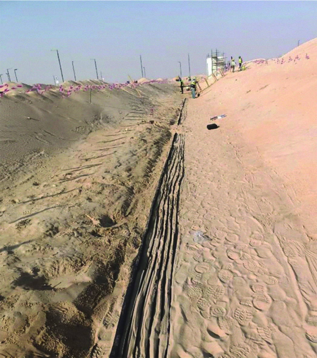
Figure 5: Installation of CP Cables in The Same Trench of the MMO Linear Anode.

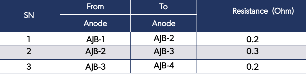
The CP system must then be examined to confirm the proper installation of all components. It is crucial to verify the connections and continuity of the positive anode cables. Resistance measurement between various anode feeders is required to ensure electrical continuity, as well as between different main positive cables. The resistance reading should be less than 1 ohm. Sample results of the continuity test are illustrated in the tables below.

Table 1. Anode Feeders Continuity Test Sample.

Table 2. Main Positive Cables Continuity Test Sample
During CP commissioning activities any temporary sacrificial anodes must be disconnected and the piping given 96 hours to depolarise before measuring the native potentials which were found in this instance to lay in the range -410 to -635mV copper/copper sulphate (CSE) with an average of -550mV. Thereafter the permanent CP was commissioned and energised and the piping allowed to polarise for 48 hours at 4.5Volt/2.2Amp setting. ON ‘pipe to soil’ potentials were measured at all test stations and the Instant-Off pipe to soil potentials were then measured at DC coupon test stations. Both ON & Instant-Off potentials did meet the required CP criteria as specified in Saudia Aramco COMPANY specifications. The records of Native, ON and the Instant-Off pipe to soil potentials are illustrated in the tables below.

Table 3. Native, ON and the Instant-Off Pipe to Soil Potentials at DC Coupon Test Stations.
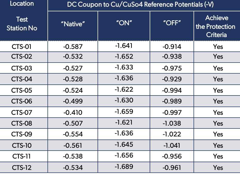
Table 4. Native and ON Pipe to Soil Potentials at Test Stations

Summary

Process equipment reinforced concrete foundations and electrical plant grounding are usually an integral part of the plant. Shielding of underground piping network in congested oil and gas plants is one of the major problems when CP is applied for its protection from external corrosion. Not only is a significant amount of protective current consumed by these elements, but also, they restrict the flow of protective current to the intended structures from a conventional, distributed or remote ground bed. CP of plant piping where current leakage and stray current caused by reinforcement concrete foundations and grounding rods are a real problem.

MMO Linear anodes are a modern solution that can simply be laid alongside a new pipeline and current distribution and polarisation formation are normally better in case of anodes installed close to the pipeline, MMO linear anode is an effective method to protect the plant piping against soil side corrosion.

The utilisation of MMO linear anode for plant piping protection will also lead to a substantial decrease in project installation and maintenance expenses, as well as improved performance in comparison to the traditional method of CP distributed anode. In this particular case study, the approach of Linear MMO anode to be utilised for plant piping protection resulted in revising the initial plan to drill and install 50 distributed anodes. As such, significant cost savings were realised resulting in approximately 3850 meters of cable trenching and 50 drill anodes with total depth of 250 meters were eliminated in addition to avoiding the need for anode bed replacement for an extended period, ranging from 25 to 40+ years, can result in significant cost savings in terms of capital cost.

References

  1. ISO 15589-1, Petroleum, petrochemical and natural gas industries — cathodic protection of pipeline systems, Part 1: On-land pipelines, ISO, 2015.
  2. NACE/AMPP SP0169, Control of external corrosion on underground or submerged metallic piping systems, NACE International, Houston, 2013.
  3. EN 14505, Cathodic protection of complex structures, BSI 2005
  4. NACE/AMPP SP0286, Electrical isolation of cathodically protected pipelines, NACE International, Houston, 2002
  1. A Nordquist, “Cathodic protection design considerations in congested area facilities,” Paper No. 10900, in Proceedings of the NACE/AMPP Corrosion Conference & Expo 2018, NACE/AMPP, Houston, TX
  2. A W Al-Mithin, “Effectiveness of cathodic protection system for buried flow lines near gathering centres using continuous linear anodes,” Paper No. 0001530, in Proceedings of the NACE/AMPP Corrosion Conference & Expo 2012, NACE/AMPP, Houston, TX
  3. M Attarchi, “Simulation of linear anode-pipe cathodic protection system: primary and secondary current and potential distribution analysis,” NACE/AMPP Journal of Science and Engineering, 75(9), 1128–1135.
  4. Z Chaudhary, “Cathodic protection of piping network in congested area of a petrochemical plant,” Paper 05050, in Proceedings of the NACE/AMPP Corrosion Conference & Expo 2005, NACE/AMPP, Houston, TX.
  5. T Huck, “Linear anode for pipeline rehabilitation – thirty years later,” Paper No. 19993, in Proceedings of the 18th Middle East Corrosion Conference and Exhibition (MECC) 2023.
  6. A H Mohammad, “Problems associated with remote anode beds in very low resistivity soil for protection of piping networks in congested areas of a petrochemical complex,” Paper No. 03713, in Proceedings of the NACE/AMPP Corrosion Conference & Expo 2003, NACE/AMPP, Houston, TX.


Advancing Subsea Pipeline Corrosion Inspection, Current Capabilities and Future Requirements

Advancing Subsea Pipeline Corrosion Inspection, Current Capabilities and Future Requirements

Meet The Author

Neil M Cowin, MSc, CEng

Neil M Cowin is an experienced Integrity Manager specialising in topsides facilities, pipelines and subsea engineering, with a strong focus on corrosion and HSE management. An innovative thinker with extensive experience delivering strategic, operational and technical integrity services for large-scale offshore and onshore assets. Possesses in-depth expertise in process and operational integrity, inspection, maintenance, corrosion engineering, materials selection and integrity consultancy for pressurised systems, including subsea facilities, pipelines and topsides.

Highly skilled in technical data acquisition for integrity, inspection and maintenance planning, and in the development and consolidation of equipment databases. Demonstrates strong knowledge of inspection policies, procedures, scopes and methodologies, including risk-based inspection systems and written schemes of examination. Acts as Technical Authority for pressure systems and provides specialist input to EPC design reviews. Experienced in CP design and retrofit programmes, defect assessment, fracture mechanics, remaining life assessments and repairs in accordance with API 579, PD 5500 and ASME VIII.

Introduction

Subsea inspection has developed NDE equipment from those techniques developed for the inspection of pipelines and piping for topside oil and gas service. Especially techniques such as automated UT, ACFM, Eddy Current, Pulsed eddy current, radiography, Acoustic Resonance [ART], now CT – radiation scanning Tomography for deepwater pipelines at 3000m water depths even was utilised subsea to some extent. New developing techniques, per thermography and CT tomography, are also now employed to achieve data for inspection of pipelines and have been useful for inspection of bundles for subsea service. These techniques have also been developing to allow inspection of flexibles to some degree of success, and this is ongoing.

The issues have also related to the factor that external coatings are to be removed to allow such inspection for certain techniques especially that for automated UT. This is because UT cannot define defects below insulative coatings and FBE. The power requirements for ultrasound are the main restriction for not allowing signals to be received from the substrate below coatings such as 3 layer or cement clad pipelines with carbon steel ROD reinforcement cages within the cement cladding upon the pipelines.

All techniques have to be developed and managed via a surface vessel and supported by ROV’s in the main to allow inspection below water. The depths range but presently inspection can bemanaged up to 250 m depth pipelines for the majority of the techniques and for ‘CT-Scanning radiation Topography’ the equipment is viable to 3000 m water depth at significant cost. Thus, analysis is called upon to enable definition of the NDE techniques which will lend themselves to allow inspection of pipelines subsea as a screening approach without removal of external coatings and allow inspection of the WET through FBE, 3-layer coatings and also cement clad weight coated pipelines.

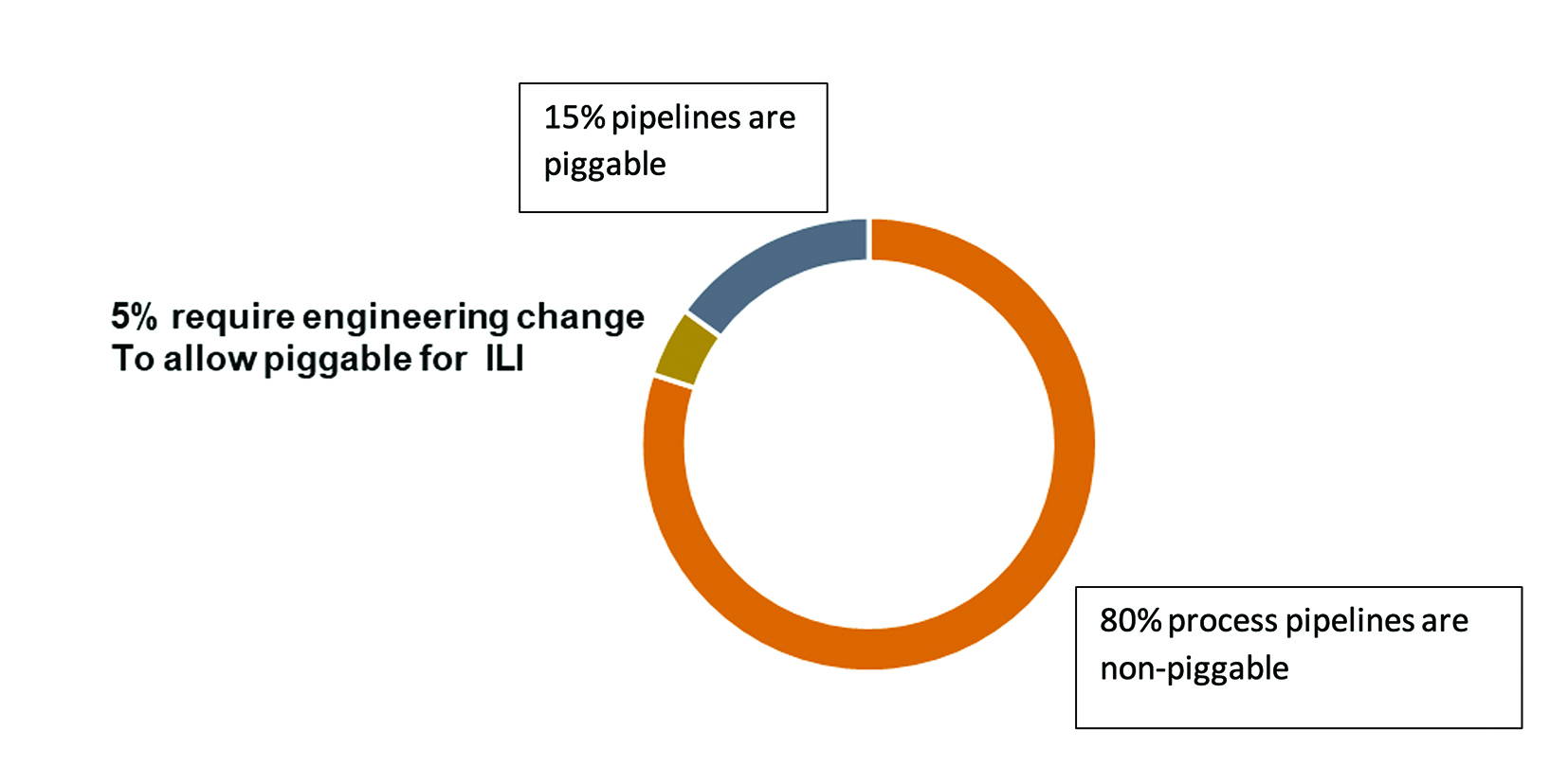
It is to be recognised that 80% of pipelines are non piggable and thus ILI as a method for inspection on many occasions is not viable subsea without expensive modifications, e.g. temporary pig traps (subsea or portable constructed on topsides).

Methodology Outlining the Status of Subsea NDE and Further Requirements

The initial trial inspections were based upon NDE techniques as stated surrounding topside and onshore piping inspections. These being based upon ASME section V standards capabilities and API 571.

These were ‘UT’, ACFM, Eddy Current then moving forwards to Pulsed Eddy Current, Automated UT arrays, Eddy Current arrays, development of a radiography tool then recent periods have witnessed ‘CT- radiation Tomography’ and also developing Thermography being utilised as a subsea inspection. The other advancements has been ‘ART’ the Acoustic resonance UT array technology.

It began with use of divers and moved forwards to the use of ROV’s and surface vessel management and scope developments. The stated crux is that external coatings mainly have to be removed, which often causes concern. Techniques have advanced with ‘ACFM’ and ‘Eddy Current’ and specialistic Pulsed Eddy current and newer developed CT- radiation Tomography which has allowed WT of the pipelines to be assessed without the removal of coatings.

It has to be stated that the goal is to achieve a screening protocol of investigation of subsea pipelines without coatings removal in the
long term. The development of ‘ACFM’ (alternating current field measurement) has been born from its usage with structures inspection for defining flooded members for offshore jackets which is a standard inspection undertaken at defined frequencies with the assistance of ROV’s and an inspection vessel. Initial inspections using automated ‘UT’ again are defined by assessment by RBI across the seabed review of the most likely sites where coatings can be removed in 3m sections to allow a ‘UT’ array tool to be attached and rotated around the pipeline up to 3 or 5m sections is the normal status.

Pulsed Eddy Current (PEC)

PEC subsea inspection is used to detect and map corrosion and general wall thinning in ferrous metal assets, such as offshore risers, pipelines, and submerged structures.A probe with a coil is placed on the surface of the asset being inspected.

The coil creates a magnetic field that passes through any layers of coating, insulation, or marine growth to the metal component. The current is then quickly shut off, causing a sharp drop in the magnetic field. This sudden change creates eddy currents within the pipe wall. The eddy currents spread inward and decay. The rate at which they decay is measured by the probe. A thinner wall (due to corrosion) will cause the eddy currents to decay faster, while a thicker wall will cause them to decay more slowly. This provides a reliable estimate of the remaining wall thickness.

The benefits and features that make PEC a developing NDE technique for subsea pipelines and structures inspections includes No surface preparation: The technique can penetrate concrete weight coatings, thick insulation, and marine growth, eliminating the need for costly and time-consuming cleaning.

• Automation and accuracy: Automated systems and array technology enable consistent performance, improved probability of detection, and highly accurate positioning.

• Efficiency: It allows for rapid, quantitative screening and corrosion mapping of large areas without shutting down production. • Remote deployment: Subsea PEC systems are often mounted on remotely operated vehicles (ROVs) for deep offshore inspections, reducing the need for divers.

• Versatility: The method is effective for a wide range of underwater assets, including pipelines, risers, caissons, and underwater storage tanks.

As an example of pulsed Eddy current underwater probe capabilities. Underwater probes can tackle offshore inspection applications, even through marine growth requiring no surface preparation. The standard underwater PEC probes are watertight to 100m (330 ft) deep and feature a long cable. These probes are operated with the proven PEC system.

The status LEDs embedded in the probes ensure better control and synchronisation of the diver with the topside inspection team. Diver deployed inspectors can scan components as thick as 100 mm (4 in) as well as insulation and marine growth as thick as 300 mm (12 in).

It is understood the critical importance of maintaining the integrity of underwater assets. That’s why underwater pulsed eddy current probes are designed and built to the highest standards of quality and reliability. With advancing ‘PEC’ inspection solutions,’ PEC’ can detect corrosion and defects in underwater structures quickly and accurately, ensuring the safety and longevity of subsea structures and assets. There are now viable ‘PEC’ Technologies for the most advanced, effective, and dependable inspection challenges available in underwater environments.

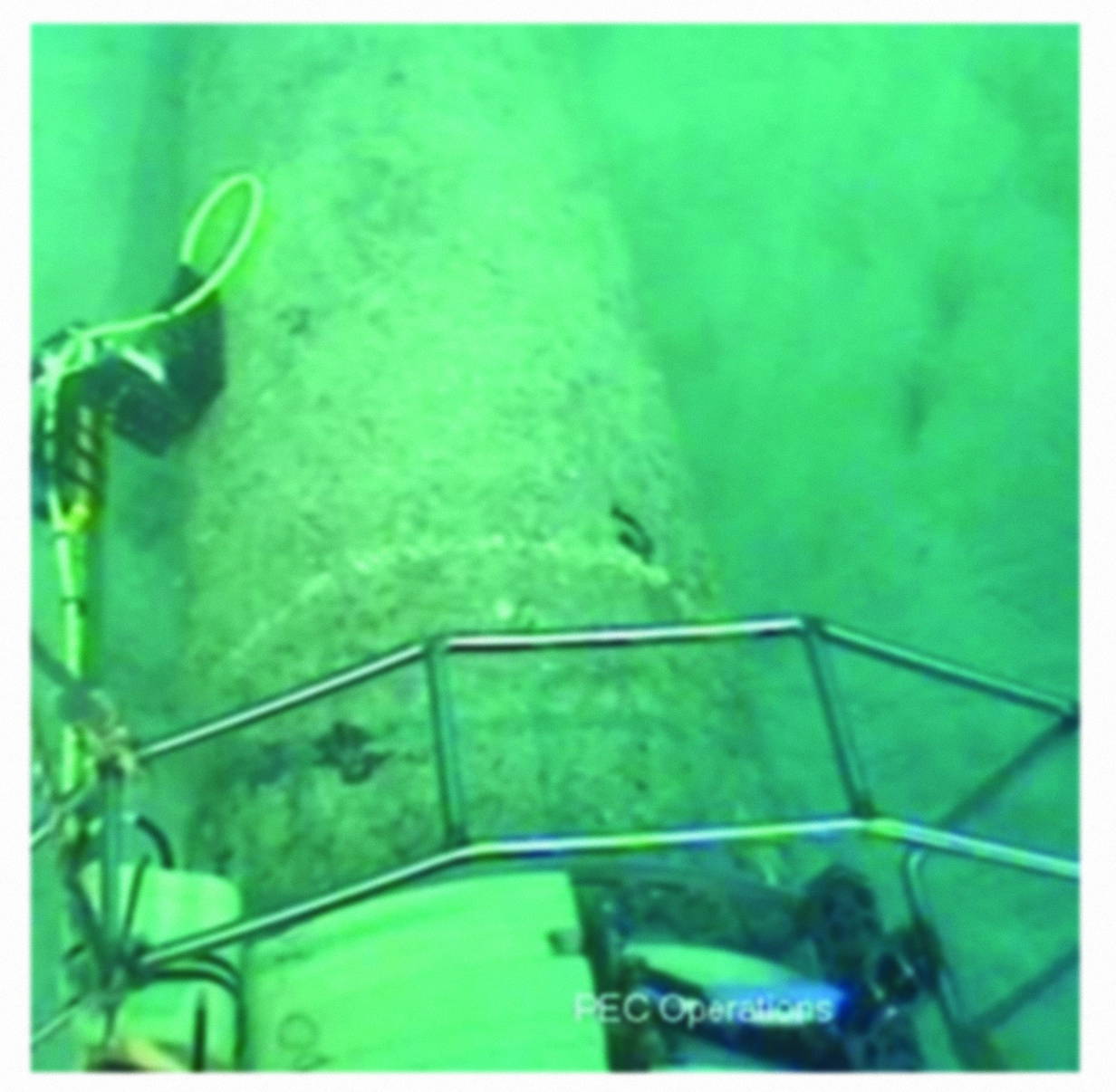
Figure 1: Example of ROV Conducting a PEC NDE Inspection on the External Surface of a Cement Clad Pipeline.

The ACFM (Alternating Current Field Measurement) subsea crawlers offer smart deployment and operation:

– Motorised mechanisms allow the probe to be deployed accurately over the weld to be inspected.
– Can be deployed by ROV or via deck launch
– Can be deployed with ACFM, ART, or PEC
– Has typical inspection speeds of 30mm/s (1.18ins/s), with a multiple pass inspection being 15 mins/m
– Is rated for water depths up to 150m (493ft)
-Can easily manoeuvre on diameters greater than 760mm (30 ins)
– Uses a closed-loop feedback motor control for accurate weld tracking and a uniform scan speed
– Can inspect through paint and other coatings – Is tolerant of residual marine growth.

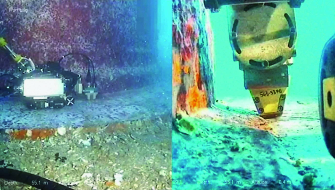
Figure 2: Example of ACFM Around a Seam Weld Subsea.

Acoustic Resonance – Subsea Operability

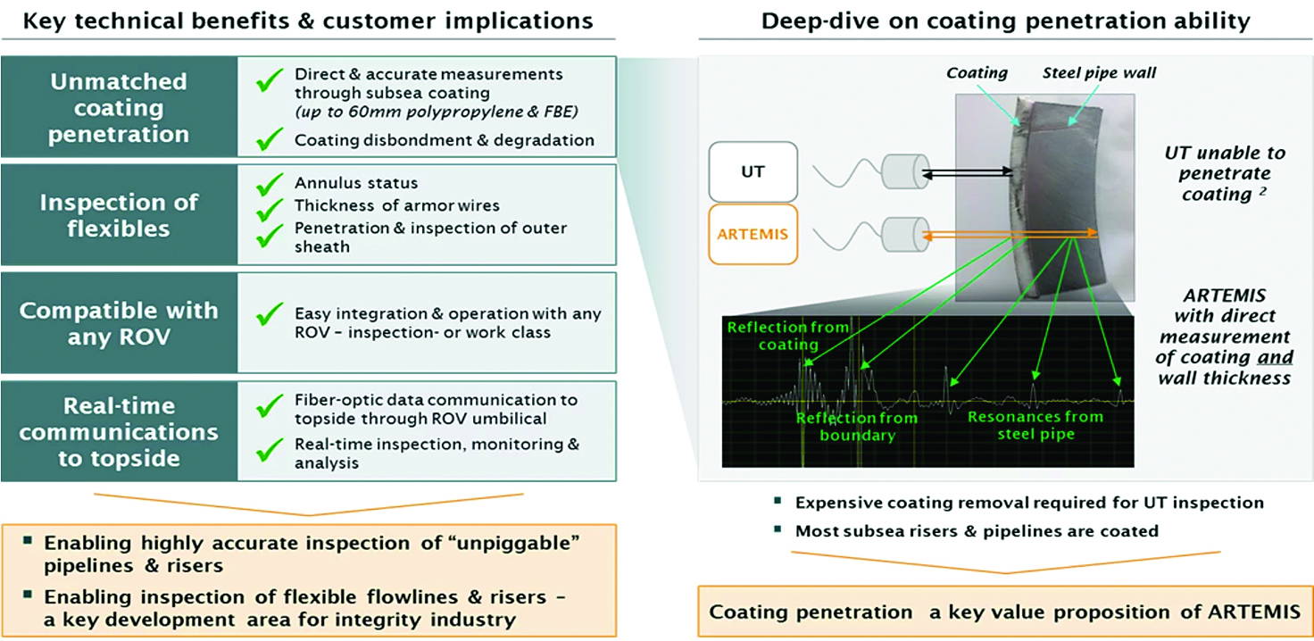
Subsea’s ART is its patented, ultra-wideband acoustic inspection technology, which offers penetration and measurement capabilities through coatings, exceeding those of existing inspection technologies. In addition to analysing the material resonances (frequency domain), the technology uses time-of-flight measurements (time domain), which provides accurate external geometry measurements for ovality and dents. ART uses a transducer shooting a broadband (multiple frequency) sound signal toward a target such as a pipe wall. The signal duration is sufficiently long to generate oscillations in the target. As the oscillating target continues to be struck by the sound signal, the resonance greatly amplifies the oscillations. The resonating frequencies (frequency domain) are characteristic of the thickness and material of the target. Attaining accurate data with direct measurement of thickness makes it possible to calculate corrosion rates more effectively and cuts down on the number of inspections that are ultimately required.


Figure 3: Summary of Proficiency of Acoustic AUT Subsea and Capabilities.

CT – Scanning or Computed Tomography by Radiation Scanning Data.

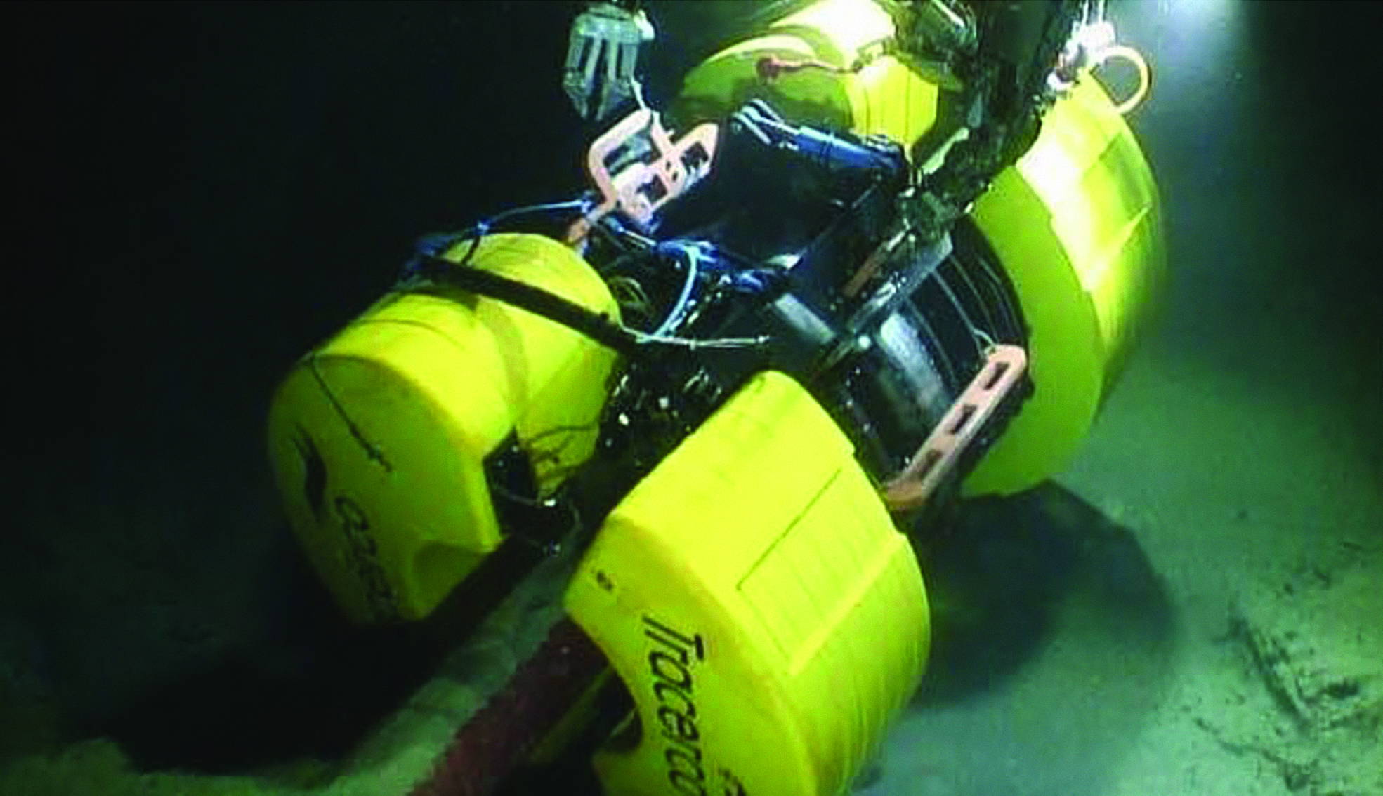
A major development in deepwater pipeline inspection methodology in recent years has been the integration of subsea CT scanning technology. This enables the delivery of critical flow assurance and integrity data without the need to remove the pipeline’s coating. Subsea CT scanning technology offers operators an enhanced understanding of their pipeline, its coating and its process fluids—while allowing the asset to remain fully operational. Using CT technology, an external scan and detailed high-resolution images of the pipe wall can determine precise sizing of wall thicknesses in minutes. Tomographic imaging can identify flaws within a pipe’s walls, pinpoint the location, and assess the volume and density of any material or deposits in the pipe.

A major development for the industry has been the introduction of methodologies and technologies that enable the online inspection of piggable and unpiggable deepwater pipes from the outside without the need to remove protective coatings or shut down production. Usually deployed using an ROV on a variety of pipeline designs, advanced deepwater inspection systems can provide insights on both internal and external corrosion, detect blockages and ascertain flow issues. They offer the industry a solution for pipelines that simply cannot be inspected by traditional means and can avoid intrusion and loss of production while providing a significant reduction in campaign costs.

An example is given below of the CT radiation tomography scanner developed by the vendor for up to 3000 m operations depth, thus 10,000 ft capabilities for placement onto a pipeline and viability through coatings for developing pictures through the cross section noted below. Deployed by ROV and operated by umbilicals for power supply.

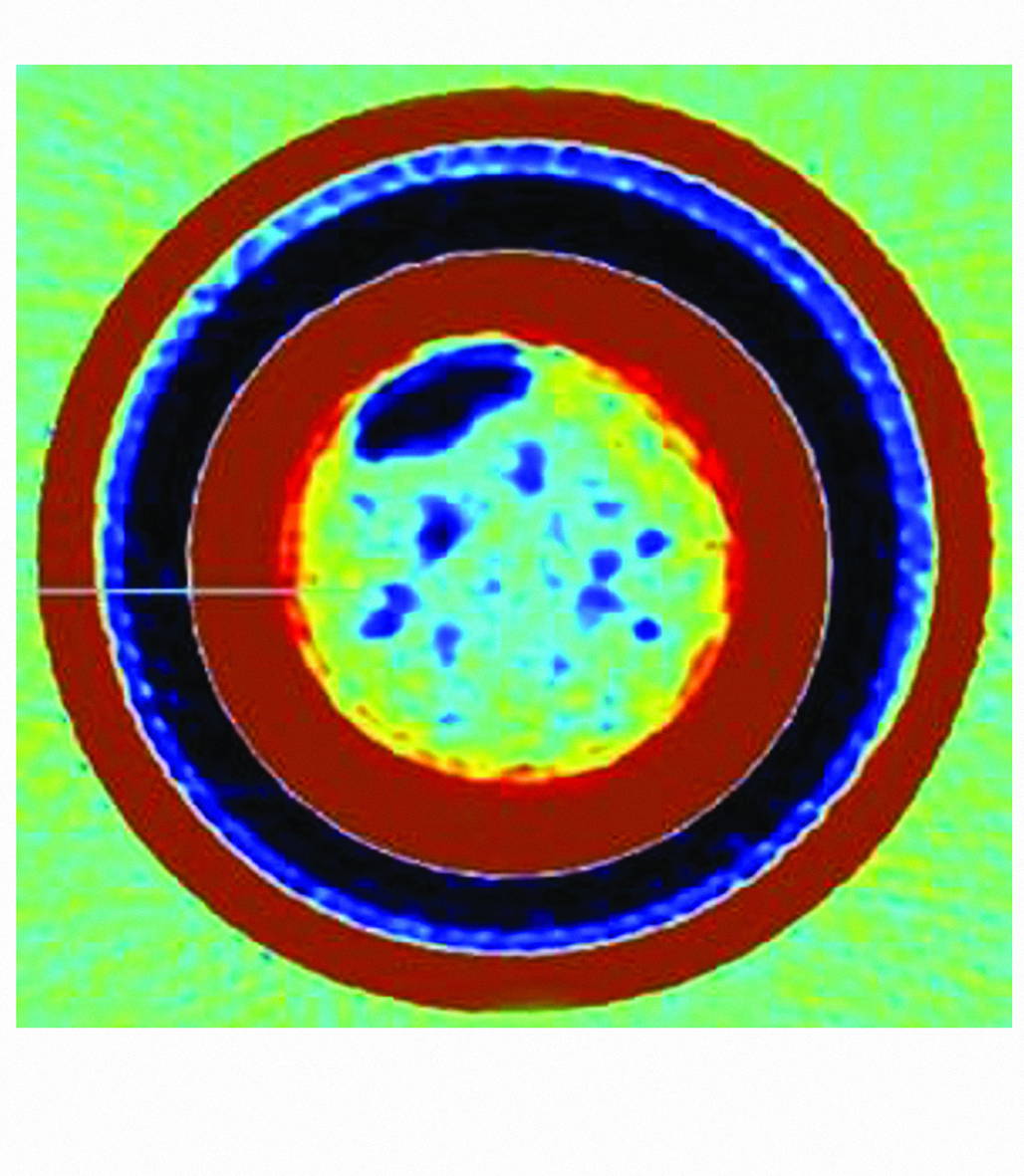
Figures 4 and 5 (Inset): CT Thermography Show Extent of Deposit Inside the Pipeline

This subsea pipeline inspection system was designed to deliver accurate material results and distinguish between wax, sand, hydrate, asphaltene or scale deposition within a density differential as low as 0.03 g/cm3. By gathering real-time data on a variety of pipeline integrity issues, including pipeline corrosion, erosion, pitting and wall thinning, modern inspection technologies enable operators to effectively determine the length of time a pipeline can be extended past its original design life. This can help eliminate the operating costs associated with designing a new section of pipeline, recommissioning, pipeline modification, and the time and risks associated with coating removal/reapplication and long and expensive vessel hire.The introduction of advanced fast screening technology can reduce overall scan time by up to 80% in some cases, which means operators can capture more data from a single pipeline inspection to help them improve and enhance the efficiency of existing pipeline models.

Deepwater pipeline inspection systems are often deployed in conjunction with pipeline screening technology to locate blockages
in subsea pipelines, which can be many miles in length. Accurately detecting the location of blockages caused by a buildup of deposits
is an ongoing issue within pipeline operations. Modern technologies can offer flow assurance screening capabilities to identify areas for further investigation and are often deployed as a pre-cursor to the pipeline inspection system. Advanced screening technologies, such as CT Radiation tomography, allow the rapid screening of pipelines
for content and deposit buildup and can provide the capability to screen several kilometres of line at typical speeds of up to 100m
per hour without interruption to production. Non-intrusive with no requirement for pipeline preparations, these technologies can measure flow assurance from the outside of the pipeline, avoiding the need to remove protective coatings. The most advanced screening systems are capable of being deployed at depths of up to 3,000m (10,000 ft) and have been deployed to inspect a wide range of pipe diameters and systems including rigid coated or uncoated pipe, pipe-in-pipe, bundles and flexibles. They can provide a detailed pipeline profile by identifying the mean densities of contents and the volume of material based on measured densities, detecting the location of deposit buildup, measuring the density profile of the pipeline, and analysing any detected anomalies. Once the screening system has located any suspected blockage, the Discovery inspection system can be deployed to accurately characterize the precise type and scope.

Corrosion Types and Threats in Coated Pipelines

Coating Types

• 3-Layer Systems + Cathodic Protection (CP)
• Cement CladdingCoating Tupes
• Fusion-Bonded Epoxy (FBE)
• Primary Corrosion Drivers:
• Produced water retention (with CO2, H2S, scales, and deposits)

Corrosion Threats

Exacerbation by CO2, H2S, and chloride salts.

Microbiologically Influenced Corrosion (MIC): Anaerobic bacteria in risers insulated for waxy crudes Vapor-phase & condensation effects.

Integrity Risks

Cracking risk in 40 c –120 °C temperature range
Damage to outer coatings → ingress of water/salts
High corrosion rates observed on carbon steel (CS) and alloy pipelines and 316L ,plus martensitic and 400 series Cr alloys
Reduced CP protection effectiveness

Inspection History

• Alloy pipeline threats not fully assessed for SCC/CSCC under coatings and insulation
• Early inspections limited (partial UT with sampling boxes in the 1980s–1990s; partial ROV coverage)

Pipelines coated to FBE specs before cement/3-layer systems

NDT Strategies for Non-piggable Pipelines
Objective: Inspect 40-year-old coated subsea lines where pigging is not feasible. Scope: Pipelines, risers, flexibles, bundles

Prioritisation

  • Focus on insulated systems (dew point, wax control)
  • High-risk streams first (gas & HC production)
  • Then secondary streams & utilities

Available NDE Techniques

Automated UT arrays by subsea collars – The external coatings have to be removed for UT automated arrays to be operable.

  • Pulsed Eddy Current (PEC) – wall loss through coatings, average 250m water depths are viable.
  • Guided Wave UT (LRUT) – long-range screening, coatings have to be removed for access of the array collet to the
  • ACFM – crack detection at welds, ROV-deployable, 150m water depths and viable for deeper
  • EMAT – corrosion under supports, no NDT couplant needed
  • CT- Radiation Topography- deepwater use up to 3000m depth is viable through coatings.
  • CP Surveys by ROV inspection vessels – voltage potentials & potential gradients to assess external pipeline coating and anode condition and longevity.
  • Flexibles & Bundles: Annulus testing to 30 m depth maximum, fatigue/curvature monitoring over the arch buoys for structural integrity in water depths up to
  • Process Data Correlation: Inhibitor performance, water cut, salts, Fe counts, bacteria.

General Guidance and API Standards

Recommended guidance includes:

A Guideline framework for the integrity assessment of offshore pipelines. DNV Technical Report number 44811520 was part of regulator – HSE KP 3 key performance, type 3 assessment circa 2009 onwards. Especially for Riser integrity management and inspections refer DNV-RP-206.

The CRUX of the matter is to design out the threats by ‘process review’ and replace by inspection equipment especially deepwater subsea production to ensure internal pigging requirements. API 571-Damage mechanism affecting fixed equipment It covers ‘NDE’ and specifications. Technically it does cover onshore facilities more so than offshore.

Way Forwards

It is important to develop a progressive R&D program for screening subsea, coated, non-piggable pipelines.

Discussion

Some key outcomes in these processes to date have been:

  • Assessment by a topography review of the seabed profile did not always define defects present. For non- piggable pipelines it has proved verys difficult to satisfy all requirements.
  • Design basis has generally been to rely on internal inhibition and coatings and core ‘CP’ for
  • Flexibles have been difficult to inspect effectively, due to polymer Focus has been on cracking of armour wires. Assessment of flooding of the annular gap is was achieved via a defined vacuum test period inspection technique in standards (note max 30 m depth viability below water).
  • Latterly CT-Tomography and recently subsea Thermography has been more valued, as has ‘ACFM’, ‘ECI’ and ‘PEC’ because of its capabilities through % It has advanced even further since.
  • Subsea engineers and integrity managers have Utilised ‘ECI’ and ‘UT’ crawlers but removed % coatings from pipelines in majority of cases to obtain a % inspection.
  • The ‘NDE’ focus over the last 20 years has been partially

As the oil and gas industry considers exposure to more challenging and deeper environments, the continuous development of innovative technology will be essential in supporting performance improvements.

As exploration and production go deeper, pipelines will likely have to overcome even greater issues than at present when it comes to integrity and flow assurance. Being able to scan and inspect these assets as accurately and as quickly as possible while allowing production to continue will enable operators to make critical informed decisions, safely and efficiently. Great strides have been made in the screening and inspection of deepwater pipelines, making what may have once been regarded as impossible now possible. However, the industry must

continue to push the boundaries of products and services in the pipeline inspection sector to solve the seemingly impossible problems of the future.

Develop ‘NDE’ Technology for screening the ‘WT’ below the external of subsea coated pipelinesesepcially cement coated pipelines.

Figure 7: Project Consideration’s

Conclusions

Subsea Inspection of Non-Piggable Pipelines: Key Challenges & Future Needs: The development of integrity for subsea pipelines external inspection and especially Risers to facilities are core Major threat for gas leaks or oil leaks within the North Sea (onshore & offshore) and other international zones. Developing techniques for NDE have been derived from what is traditional corrosion management inspection techniques from API 571 approach. These techniques noted AUT, Eddy current, PEC and ACFM were utilised on subsea structures for assessment of corrosion and flooded member detection. They were also extensively utilised for inspection of caissons for utilities (sea water lift for fire mains water for deluge) and injection of disposal water. 40 years of data gained mainly by the removal of coatings subsea and inspection by UT arrays or other techniques such as Eddy Current PEC, even percentage of radiography has often been the best solution’ noting that:

  • Current practice: is to remove circa 3m to 5 m width bands of external coating in low-lying areas, analyse WT% by NDE mainly automated UT arrays.
  • This principally has been applied mainly to 6”–10” flowlines size ranges especially in the Gulf
  • Thus, the weight coated pipelines of Cement cladding up to 150mm (5.9”) thick has created

The noted subsea Failures have been linked to process variations, material selection, and limited NDE capability subsea and also requirements for

a screening approach for pipelines coated with 3 layers (polyethylene, polypropylene, PVC and FBE) or more so cement clad pipelines.

Future Needs

Industry requirements continue to develop at a rapid pace.

  • Advanced ‘CT-Topography’, Thermography & ‘ACFM’ (beyond welds) have the current viable capabilities for subsea equipment enclosures for 3000 m water depths
  • Automated NDE for thicker coatings is a real focus for inspections subsea both for the depths noted and deeper pipelines projects without external coatings removal especially cement clad weight coated
  • High frequency ‘PEC’ pulsed eddy current & ‘ECI’ Eddy Current probes, to enable definition and higher accuracy for pipeline ‘WT’ below cement especially and Also to develop subsea equipment enclosures for PEC and ACFM to equally deepwater depths presently 250 m operability and require developed to 3000 m (10,000 ft) water depths.
  • Need to explore the viability of Electro-Magnetic Resonance (EMR) for subsea inspections of external coated pipelines as a screening tool to analyse pipeline ‘WT’.

It is ongoing techniques such as Electromagnetics and acoustic resonance and ‘ACFM’ that will require to be advancing with vendors and technologists in the ‘NDE’ forum and certainly the subsea engineering forum can supply these advancements to the required pipelines and structures to enable a higher definition of screening NDE equipment subsea for the oil and gas industry to enhance and ensure reliability and integrity of pipelines and structures.

References

  1. API 571, Recommended Practice for Identifying and Evaluating Damage Mechanisms Affecting Fixed Equipment in the Refining Industry, American Petroleum Institute.
  2. ASME Section V, Non-Destructive Examination of Pressure Systems,
  3. DNV, Technical Report 44811520: Integrity Assessment of Offshore Pipelines, DNV.
  4. DNV-RP-F103, Cathodic Protection of Submarine Pipelines,
  5. DNV-RP-F113, Repair Strategy for Subsea Pipelines,
  6. DNV-RP-F116, Integrity Management of Submarine Pipeline Systems,
  7. PD 8010, Subsea Pipelines, Part 2 and Part 4: Design and Integrity Management of Subsea Pipelines,
  8. Practical NDE knowledge from project experience and
  9. Presentations and technical details from NDE suppliers within the
  10. Technical knowledge of subsea NDE scopes gained over 35


STGB Report  – Introducing Our New Surface Treatment Scheme Manager (STSM) – Grant Wright

STGB Report – Introducing Our New Surface Treatment Scheme Manager (STSM) – Grant Wright

The Institute is pleased to announce the appointment of Grant Wright as Surface Treatment Subject Matter Expert and Scheme Manager (STSM). Grant joined us on 1 March 2026 and has recently completed a handover period with Jane Lomas, who is retiring from the role.

Grant brings over 30 years of experience in protective coatings and passive fire protection (PFP). He began his career as an apprentice spray painter before progressing into industrial coatings and metal preparation. Early in his career he worked within the family coatings business, followed by roles covering both automotive and industrial coatings. He subsequently gained 13 years of experience in the energy industry. Grant has extensive hands-on experience and views surface treatment as a complete science, extending far beyond the application of paint. In recent years he served as the focal point for Stork Technical Services on Dana Triton Asset before moving to the role of Fabric Maintenance (FM) Manager for Sonomatic UK projects.

Based in Motherwell, Scotland, Grant currently serves as technical FM lead within KAEFER’s Energy Division, where he leads his own team of Level 3 inspectors. Grant has also been progressing through the Institute’s Engineering Council (EngC) professional registration scheme, supported by Vice President Anthony Setiadi. He initially achieved Incorporated Engineer (IEng) status and is now working towards Chartered Engineer (CEng).Following completion of ICorr training courses and joining the Institute as a TICorr member, Grant progressed to MICorr membership and is now aiming to achieve FICorr in the near future.

Grant is also a valued member of the reformed STGB committee, which has recently been driving a number of key improvements within the institute’s surface treatment training scheme.
He can be contacted in his new role at STSM@icorr.org.

We wish Grant every success in his new responsibilities.Although stepping down as STSM, Jane Lomas will continue to support ICorr through her work on the Council and by delivering her Fundamentals of Corrosion course, with the support of Tony Risk, ETGB Chair. Her next course is scheduled to run from 14 to 18 September 2026.

For course registration or to enquire about other ICorr training courses, please contact admin@icorr.org

Registration is Now Open

Registration is Now Open

ICorr MIC Training Course 12th–16th October 2026

Advance your organisation’s capability in microbial corrosion management with this high impact, ICorr training programme. Designed for professionals in operations, integrity, inspection, management, design, R&D, consultancy, and utilities. The course equips participants to:

• Identify MIC drivers across a wide range of systems
• Implement targeted monitoring, mitigation, and control strategies • Lead investigations supported by robust, defensible evidence
• Influence organisational policies and strengthen MIC governance • Align internal practices with global standards and
best-in-class methodologies

Delivered by a leading subject matter expert and aligned with ICorr recognised competency framework, this course blends technical depth with practical application—empowering participants to protect assets, enhance performance, and drive meaningful organisational improvement. It contributes to Continuing Professional Development (CPD)

Certification Opportunity

Participants who successfully pass the final examination will earn the ICorr Certified MIC Technologist credential—a globally recognised mark of excellence in microbial corrosion management and a valuable step toward professional chartership.

Venue: ICorr HQ, Northampton, United Kingdom
For further information: Dr Tony Rizk – ETGBchair@icorr.org • Registration: admin@icorr.org

ICorr FOCE (MICorr) Training Course 14th–18th September 2026

Advance your ICorr Professional Membership

This industry leading course provides direct access to professional membership of ICorr, for those with relevant experience. Corrosion management, failures and remediation commonly occur throughout all branches of engineering where metals are part of the structure or process. FOCE is a corrosion course that covers the basic principles of corrosion that are needed by engineers to understand why and how failures occur, actions that can be taken to manage the ongoing corrosion and/or remediate the structure, and options to prevent further corrosion, where possible. The course is presented as a series of modules, starting with essential background information about the corrosion process and then applying the basic principles to common engineering metals, including stainless steel, aluminium, and copper alloys. Both the general and the different types of localised corrosion such as crevices, pitting, bi-metallic corrosion, etc., is considered. Common atmospheric and immersed conditions, re-bar in concrete, high-temperature atmospheres, water treatment, buried pipes, etc are considered to understand corrosion.

Corrosion management strategies, including material selection, cathodic protection, surface preparation, coatings, chemical treatments, inhibitors, etc., are included in the course. The role of the corrosion engineer is described and includes investigation of failed components, inspection, and testing of samples, with practical examples and case histories included in the course notes.

As a classroom-based course, FOCE is provided in English by
an experienced, practicing corrosion consultant. A copy of the training material is provided to each attendee. Questions and active participation are encouraged throughout the course, as many participants enjoy learning about the additional real-life examples that are provided by fellow attendees. Fun quizzes are held each morning so both the candidates and the tutor can assess their progress during the week on an ongoing basis. One-on-one sessions can be arranged where a student has a specific module requirement.

The learning modules are given over four intensive days, and candidates for the examination on the final day are encouraged to revise the material each evening to ensure that they understand the course content. At the end of the course, all attendees are given a Certificate of Attendance, which shows that they have been present for all the modules. After passing the examination, participants receive a Certificate of Achievement, which demonstrates that they have received sufficient corrosion training to apply directly. Previous attendees of the course have ranged from complete beginners in corrosion (zero previous knowledge) to practicing Corrosion Consultants.

Certification Opportunity

Participants who successfully pass the final examination will receive certification towards MICorr Professional Membership and contributes to Continuing Professional Development (CPD).

Venue: ICorr HQ, Northampton, United Kingdom
For further information: Dr Jane Lomas – ETGBchair@icorr.org • Registration: admin@icorr.org

ICorr Training

ICorr Training

Joint Corrosion Mechanisms in Stainless Steel

The Corrosion Mechanisms in Stainless Steel course offers a structured, practical overview of stainless steel behaviour in service and the reasons failures arise. The programme begins with key
metallurgy and corrosion principles, then examines the mechanisms most commonly encountered in industry, including tea staining and rouging, general corrosion, pitting and crevice corrosion, selective attack, galvanic corrosion, chloride and caustic stress corrosion cracking, polythionic acid SCC, hydrogen-induced cracking, high-temperature corrosion, microbial corrosion, corrosion under insulation (CUI), erosion corrosion and corrosion fatigue.

For each mechanism, the course outlines how degradation develops, the critical environmental and material factors, how to recognise damage in service, and which grades are most susceptible. Typical plant locations and practical mitigation measures are also covered.


Who Should Attend: Engineers, designers, manufacturers, fabricators, buyers, sales teams, distributors, maintenance and inspection personnel, and quality engineers seeking deeper insight into stainless steel performance in demanding environments.

CPD Certification: Participants receive a CPD approved certificate confirming completion and learning in stainless steel corrosion mechanisms and mitigation.

The course is delivered in collaboration with RTECH and the British Stainless-Steel Association. The next session will be held on 8th October in Birmingham, with additional dates available from mid-May.

Corrosion at Home and its Prevention

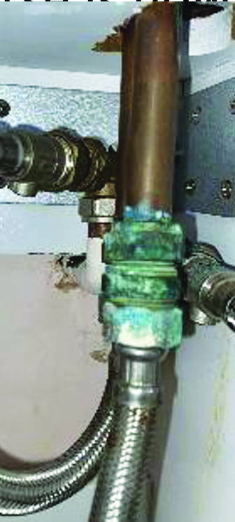
Many people assume corrosion is simply “something we have to live with,” but understanding this natural phenomenon is important. Corrosion can lead to:

Health concerns (e.g.,contaminated water from corroded plumbing)

Financial losses (repairing or replacing damaged items)

Aesthetic deterioration (rust stains, tarnished surfaces, degraded equipment)

Reduced functionality and safety (motor vehicles)


The good news is that with the correct choices, corrosion can be controlled, and often prevented, with simple, practical steps. Even basic household chemicals and a bit of common sense can go a long way in maintaining the quality, appearance, and performance of everyday items.

That’s why we’re developing “Corrosion at Home and Its Prevention”, a new awareness course designed to make corrosion science approachable and useful for everyone. The course is now at an advanced stage and has been crafted to support:

• STEM – School and student programmes
• Community groups
• Public awareness programmes
• Anyone interested in protecting their home and belongings

Our aim is to empower people with knowledge that saves money, improves safety, and reduces waste, all while making science engaging and accessible.

More details will be shared soon by our growing Institute of Corrosion (ICorr). Corrosion may be everywhere, but with the right understanding, it doesn’t have to be a problem.